Vibe design: getting an AI to model a part it will never see
A freehand sketch, seven dimensions, four wrong renders before the right one — and what it teaches about talking geometry to a machine
In two minutes, if you want an AI to model a part without opening a CAD program
- The setup: a rubber suction cup to replace, a pair of calipers, a sheet of paper — and an AI I describe the part to. It cannot see it, touch it or measure anything. Every dimension comes from me.
- What doesn’t work: asking questions. I sent a correct dimensioned sketch, the AI listed six ambiguities, I answered them one by one — and six exchanges later it still had the geometry wrong.
- What works: making it show. A wrong render, displayed with its assumptions colour-coded, gets corrected in one sentence: “the 6.5 is the shaft, not the overall height”. Two iterations settled what six open questions could not.
- The trap: my dimensions closed perfectly — 1 + 3.5 + 2 = 6.5 — on a part that was entirely wrong. A sum that adds up is not proof of a correct reading. See The trap of the sum that adds up.
- When a word is the blocker: I said “hollow”, my counterpart heard “the hole”. No amount of rephrasing helped; a diagram that colours in the volume being discussed settled it in one send.
- The material side: drawing a suction cup in 95A TPU is not drawing a suction cup. Real rubber is 40–60 Shore A, printing leaves micro-channels between layers, and on a printer with a remote extruder, flexible filament is the worst case. All of that changes the drawing, not just the settings.
- The code: the part is a 120-line Python script (
ventouse.py), every dimension a constant at the top. Changing a value and regenerating the STL takes ten seconds — which is what makes the back-and-forth bearable.
No CAD knowledge assumed. This follows the calibration of the same printer, but stands on its own.
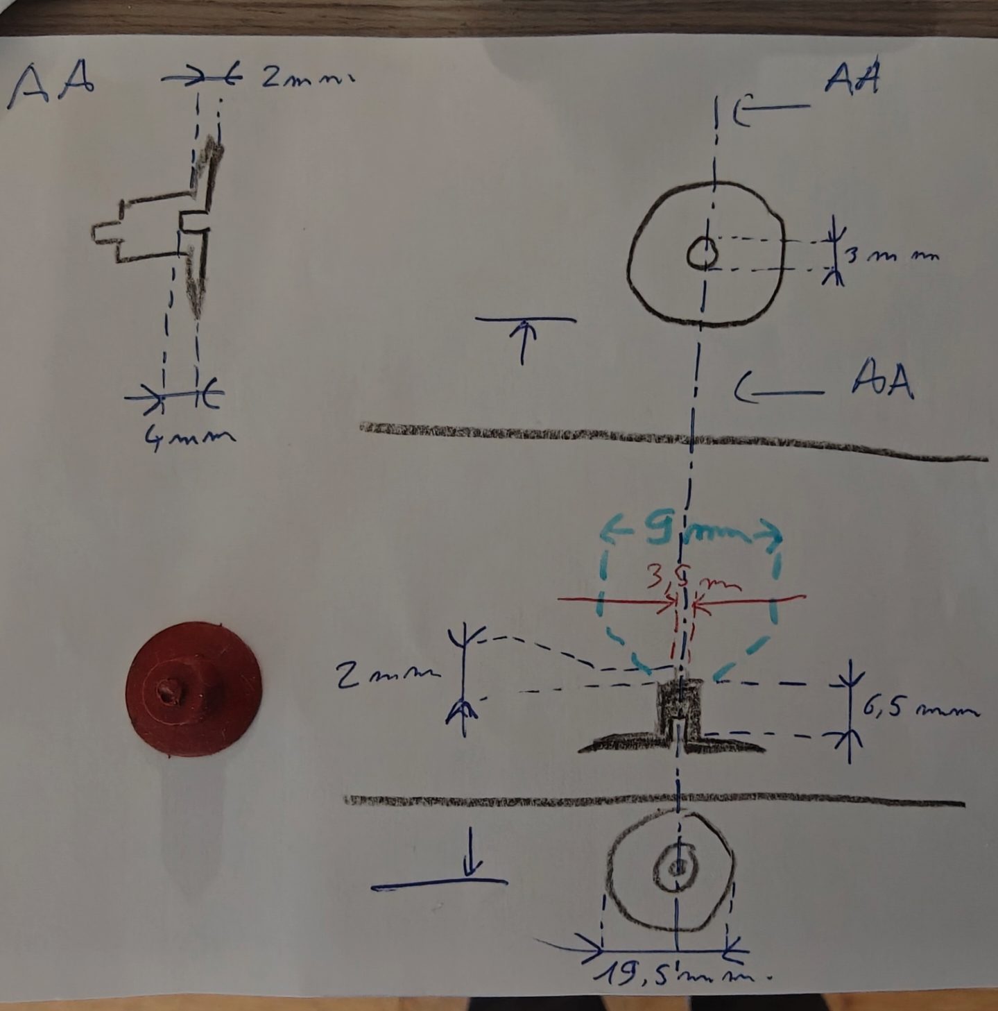
The starting point: three views, seven dimensions, and the original part next to them. This photo is everything the AI will ever have of this suction cup.
The problem isn’t drawing, it’s understanding each other
I had a rubber suction cup to remake and a freshly calibrated printer. The modelling itself isn’t the point: a suction cup is a disc, a cylinder, a stud and a bore. Any CAD program does it in ten minutes — provided you know what you’re drawing.
The point is that I wanted an AI to draw it. Not out of convenience: because I wanted to see where it breaks. An AI writing code has the shortest possible feedback loop — the code runs or it doesn’t. An AI drawing a mechanical part has no feedback loop: it cannot see the object, cannot measure anything, and its result only becomes wrong at the moment the part comes off the printer and won’t go into its socket. Everything in between is conversation.
So I made a sketch. Three views, dimensioned, tidy: what you’re taught in technical drawing. And that’s where it gets interesting, because that sketch is correct — and it wasn’t enough.
Six questions asked on my own photo
The AI’s first move, and it was the right one: don’t guess. It took my photo, dropped six numbered red markers on it, and sent the image back with its six questions attached to precise spots on the drawing.
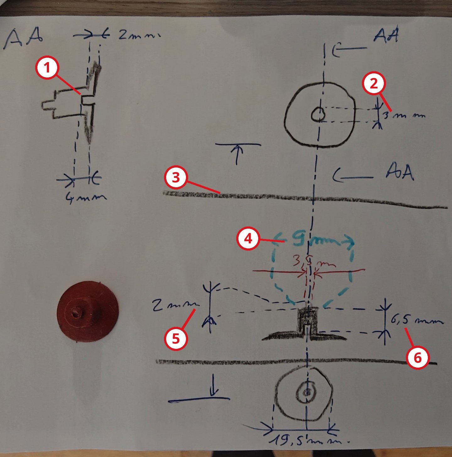
The six ambiguities, marked on the sketch itself. Annotating the image rather than describing in words: the only thing in this whole story that worked first time.
I already knew that method: it comes from the previous post, where describing a measuring gesture in prose blocked me twice in a row, and where annotating my own photo unblocked it in a single send. It works both ways. When the AI doesn’t understand my drawing, it has to show me where it doesn’t understand, not ask me to “please clarify the dimensions”.
And yet. I answered all six, one line each. “It’s a section view of the same part, it shows the thickness of the cup.” “That’s the hole, underneath the cup.” “3 mm across and 4 mm deep.” “It’s blind.” Six exact, unambiguous answers. After which the geometry was still wrong.
What a sketch lacks isn’t dimensions
Here’s the knot. My sketch carried every dimension needed. What it didn’t carry is what each dimension attaches to — and that is precisely what a freehand drawing fails to convey, whereas a proper dimensioned drawing conveys it through the position of the extension lines.
An example. I had written “6.5 mm” with a vertical arrow to the right of my section. Obvious to me: the height of the shaft. Just as obvious to the AI: the overall height, since the arrow runs from one end of the drawing to the other. Both readings hold up on a photo taken at an angle, where the arrow overshoots slightly.
Same with the hole and the stud, both roughly 3-and-a-bit millimetres, at opposite ends of the part. I wrote “3” on one and “3.5” on the other knowing which was which. Nothing on the paper said so.
What works: make it show, not say
After the sixth exchange, a change of method: instead of asking a seventh question, the AI modelled the part with its assumptions, rendered it, and sent it over — with an explicit colour code on the dimensioned section: red for the dimensions that came from me, cyan for the ones it had invented.
I looked at the render for three seconds and wrote: “from the top of the stud to the edge of the lip, the cup is 10.5 mm. 2 mm of stud, 6.5 mm of shaft, 2 mm of cup body.”
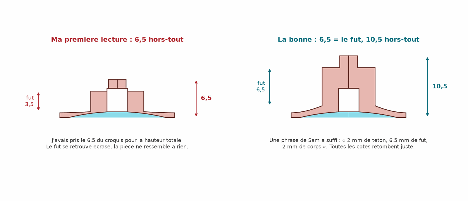
Same part, same dimensions, two readings. Left, what the AI had understood; right, what I had drawn. No question would have produced that sentence — the wrong drawing produced it.
That’s the interesting reversal. An open question (“what does the 6.5 measure?”) asks me to rebuild the context mentally, recover what I had in mind three days earlier, and formulate an answer into the void. A wrong render puts the geometry in front of me, and my eye corrects faster than my memory. The correction costs nothing any more: I can see the shaft is squashed, so I know what to say.
There’s a condition for this to work, and it isn’t trivial: the AI has to flag what it invents. A clean render, with no distinction between what came from me and what it filled in, would have had me approving a part containing five values pulled out of thin air. The cyan on the section is the admission of ignorance made visible. It is what turns the render into a measuring instrument rather than an illustration.
The trap of the sum that adds up
This is the part I find most instructive, and it’s worth pausing on.
When the AI produced its second version — the one with the shaft, still wrong — it explained that it had finally managed to place the last orphan dimension from my sketch, the infamous 3.5. Its demonstration: the cup body is 1.0, the shaft 3.5, the stud 2.0, total 6.5, exactly the overall height on the drawing. Every dimension closed on the others. It wrote, and it was sincere: “your five dimensions close on each other, which is a good sign for my reading.”
Except it was wrong. The 6.5 wasn’t the overall height, the 3.5 wasn’t the shaft height, and the reconstructed part looked like nothing on earth. The correct reading gives 2 + 6.5 + 2 = 10.5, and the 3.5 is the bore diameter — a dimension with nothing to do with a stack of heights.
A sum that adds up is not proof. With seven dimensions and a part of revolution, there are enough degrees of freedom for wrong combinations to close by chance. Arithmetic consistency is weak evidence, and it’s exactly the kind of weak evidence an AI presents with confidence because it looks like a verification. It is reasoning with the shape of a proof and none of its force.
What settled it wasn’t a calculation: it was that the drawn part didn’t look like the part on the table. The only judge here is the object.
When a word is the blocker, colour it in
One last blocker, of a different kind. For a suction cup to hold, its underside must not be flat: it rises slightly towards the centre. For want of a better word I call that the “hollow”. You press, the trapped air escapes past the lip; you let go, the rubber tries to resume its shape, pressure drops in the cavity, and atmospheric pressure holds the part down. That’s the entire mechanism.
Except my part also has a blind hole in the middle. So when someone said “hollow”, I answered: “what do you call the hollow? in the middle of the cup there’s a hole 3.5 mm across and 4 mm deep, is that the recess at the centre?”
Rephrasing would have got nowhere — the word was already taken. What worked fits in one image:
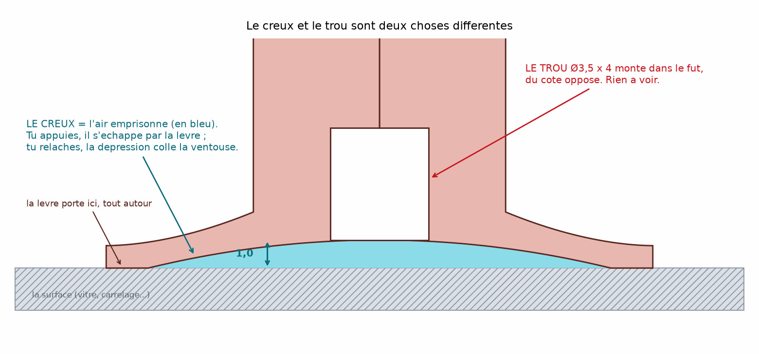
The hollow is the blue. The hole is the white one, at the opposite end. Colouring in the volume you’re talking about settles in one image what three paragraphs would not.
The general lesson: when an exchange stalls on a word, it isn’t a vocabulary problem but a referent problem. Don’t define the word better — point at the thing. In geometry, pointing is done with colour.
One detail that matters: on its first sections, the AI drew the bore as a white rectangle overshooting below the part and into the hollow, “so you can see it clearly”. I told it so — that view was less clear, because an overshooting outline suggests geometry that doesn’t exist, and it overshot precisely into the area we were trying to discuss. A technical diagram doesn’t improve by exaggerating lines; it improves by framing the relevant area and colouring the volumes.
The part
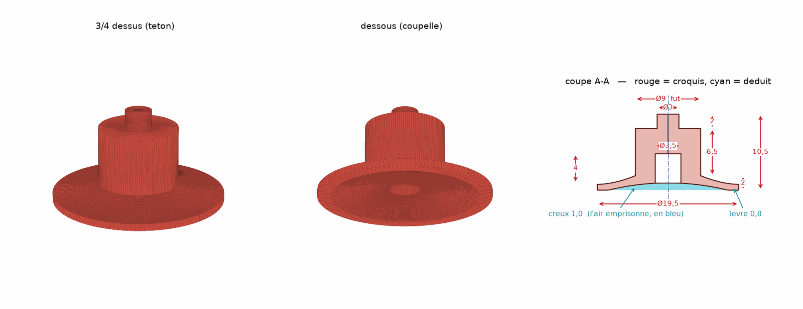
The finished part: Ø19.5 cup, 2 body, Ø9 × 6.5 shaft, Ø3 × 2 centring stud, Ø3.5 × 4 blind bore. 10.5 overall.
The model is a 120-line Python script using manifold3d, a solid geometry library. The part being a body of revolution, everything fits in a (radius, height) profile that gets swept:
def profil(n=80):
    """Closed (r, z) contour of the half-section, counter-clockwise."""
    p = []
    r = np.linspace(0, R_INT, n)                    # underside: parabolic concavity
    p += [(x, CREUX * (1 - (x / R_INT) ** 2)) for x in r]
    p += [(R_EXT, 0.0), (R_EXT, E_LEVRE)]           # lip: flat seat then flank
    r = np.linspace(R_EXT, R_FUT, n)                # top of the body, slightly domed
    t = (r - R_FUT) / (R_EXT - R_FUT)
    p += [(x, E_LEVRE + (Z_FUT - E_LEVRE) * (1 - u) ** BOMBE) for x, u in zip(r, t)]
    p += [(R_FUT, Z_TET), (R_TETON, Z_TET), (R_TETON, H), (0.0, H)]
    return p

m = Manifold.revolve(CrossSection([profil()]), 128) - trou
What makes the exercise workable isn’t the library: it’s that every dimension is a constant at the top of the file, each commented with where it came from — sketch, deduction, or assumption. Changing a value and regenerating the STL takes ten seconds. Over five round trips, that’s the difference between a conversation and a chore.
Going deeper: why a revolved profile rather than stacked cylinders
You could draw this part by stacking primitives: a cylinder for the body, one for the shaft, one for the stud, a subtracted cylinder for the bore. It works, and it’s what an AI naturally does when asked for “a suction cup”.
The problem is the cup itself. Its underside is a curved surface, and its thickness varies from rim to centre — which is what lets it deform under thumb pressure and spring back. With primitives you’d subtract a sphere segment or an ellipsoid, and the resulting thickness would become a consequence that’s hard to control.
With a revolved profile you describe both surfaces directly — the underside as a parabola z = hollow · (1 − (r/R)²), the top as a domed curve with a tunable exponent — and thickness is the difference between them, visible and controllable at every point. On a flexible part whose entire function lies in how it deforms, that’s the only parameterisation that gives you a handle.
Manifold.revolve takes a cross-section in the XY plane, spins it about the Y axis, and returns a solid whose axis is Z. The blind bore is then subtracted as a cylinder — drawn, in the preview section, exactly between its entry and its floor, with no overshoot.
Drawing for TPU isn’t drawing a suction cup
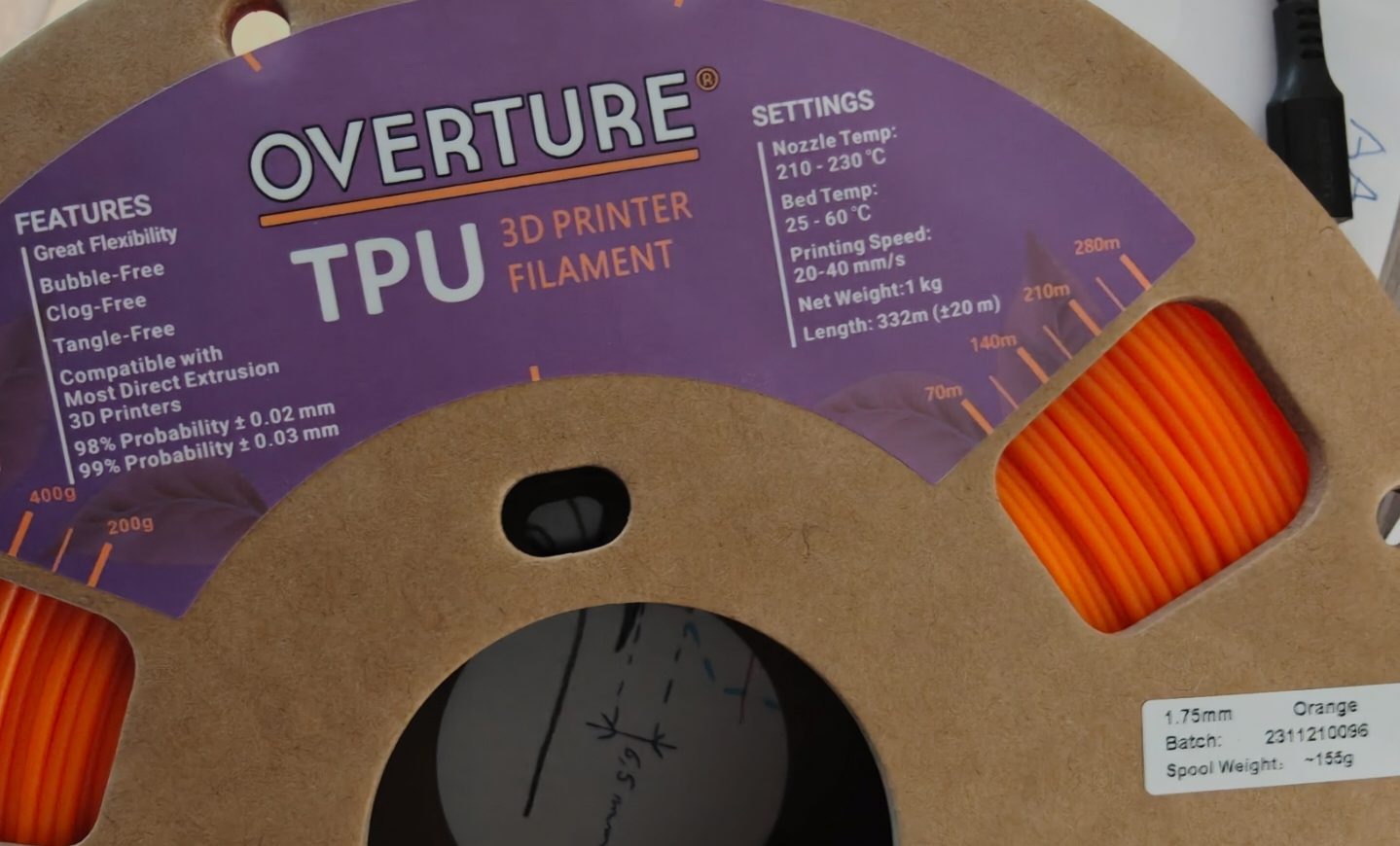
The spool that started all this. The label says 20 to 40 mm/s — while noting, a little higher up, that it targets direct-drive printers.
A real suction cup is silicone or soft PVC, around 40 to 60 Shore A. The most common TPU, the one I have, is 95A: roughly the hardness of a trolley wheel. That isn’t a settings detail, it’s a design constraint.
A thick 95A lip won’t conform to the micro-defects of the surface: it will sit on three high points and leak between them. So the lip has to be thin, 0.6 to 0.8 mm, thin enough to flex — at the cost of fragility. And it gets worse: a fused-filament part is a stack of welded beads, and between two beads there remain micro-channels. On a cosmetic part nobody notices. On a part whose job is to hold a vacuum, they’re leaks. Hence thin layers, a high temperature and a slight excess of material — not for strength, but to weld the layers to each other.
That’s the kind of trade-off a dialogue with an AI surfaces well, provided you give it the material before the geometry. Had I asked for “a suction cup” without saying more, I’d have got a 2 mm lip: correct in moulded rubber, useless here.
TPU on a remote-extruder printer: the worst case
Then it has to be printed, and that’s where my machine speaks up. On a FLSun QQ-S, the motor pushing the filament isn’t on the head: it’s on the frame, and the filament travels about 700 mm through a guide tube before reaching the nozzle. That’s a Bowden setup. With rigid filament it works: the filament behaves like a rod being pushed. With flexible filament it behaves like a spring — you push at one end, nothing comes out the other, then it all comes out at once.
Three consequences, and they show up in the slicing profile:
- Retraction. My PLA profile retracts 5 mm. On TPU, 5 mm slackens the filament enough that it can coil at the tube entry and jam — that’s the failure mode of flexibles in Bowden. Down to 2 mm, at reduced speed.
- Speed. The label says 20 to 40 mm/s, assuming a direct extruder. In Bowden, 15 to 25.
- Acceleration. On a fast delta, jolts get absorbed by the elasticity of the filament rather than by the nozzle: material goes missing in the corners. Brought down from 1500 to 800 mm/s², restored at end of print.
Going deeper: should the extruder go on the head?
It’s the question that comes up immediately: if the tube is the problem, why not mount the extruder on the head and do away with it? I happen to have a dual-drive extruder waiting, an OMG V2-S, weighing 64 g and mountable either as Bowden or direct.
The arithmetic is less favourable than it looks, because the weight isn’t in the extruder, it’s in the motor: about 215 g with a pancake motor, 365 g with a standard one. And on a delta, the effector moves in all three axes, unlike a Cartesian where a direct extruder only loads the X axis.
Now, a structure’s resonant frequency follows f ∝ 1/√m. My machine already resonates at 20 Hz, which is low; doubling the moving mass would drop it towards 14 Hz. Klipper’s documentation holds that below 25 Hz you should stiffen the machine rather than compensate — below that, the input shaper starts rounding off detail. I’d be paying for TPU comfort with a degradation on everything else, on a machine I’ve only just calibrated.
The practical conclusion: keep the Bowden, and attack the problem from the other end. The real culprit for flexibles isn’t tube length, it’s the stock single-drive extruder, under which soft filament escapes sideways. A dual drive grips it on both sides. And a 1.9 mm bore tube instead of 2.0 stops the filament buckling in the clearance. Two cheap parts that fix most of it without touching the machine’s dynamics.
What I take from it
An AI that draws has no feedback loop. It can’t see the part, can’t measure anything, and its mistake only becomes visible at print time. The whole job is to build that feedback loop by hand — and the render is it.
Showing beats asking. An open question asks me to rebuild context; a wrong drawing puts the geometry in front of me and my eye corrects on its own. Six questions didn’t converge; two renders did.
The AI must flag what it invents. The red/cyan code — your dimensions, my assumptions — is what turns a pretty render into a measuring instrument. Without it I’d have approved five values from nowhere.
Arithmetic consistency is not verification. My dimensions closed perfectly on a wrong part. An AI presents that kind of evidence with the confidence of a proof, because it has the shape of one. The only judge is the object on the table.
When a word blocks, point at the thing. No rephrasing: an image where you colour in the volume you mean.
Material comes before geometry. “A suction cup” and “a suction cup in 95A TPU printed by fused deposition” are not the same part, and you don’t get the second by tweaking the settings of the first.
And parameterisation makes it all bearable. Five successive versions, ten seconds each. Had every correction meant reworking a CAD model, I’d have given up at the second render and drawn the part myself — which, frankly, would have been perfectly reasonable.
Where things stand
As of 8 September 2026: model frozen, printing pending. The geometry is validated on the dimensioned section, the script outputs the STL and its preview, the TPU slicing profile is written. Printing waits on fitting the dual-drive extruder, then a moisture test on the filament — the spool dates from November 2023, and TPU takes up water faster even than PETG. One unknown will only be settled by trying: the real diameter of the printed shaft. Drawn at Ø9, it will likely come out at Ø9.2; in TPU that’s recoverable, the part compresses as it goes in. In PLA it would have taken three attempts.
To reproduce
What you need: the original part, calipers, something to sketch on, and a Python environment with manifold3d, numpy and matplotlib. No CAD program.
The sketch. Three views beat one perspective. But above all: write next to each dimension what it measures, in words. “6.5 = shaft height”, not “6.5”. It’s ugly on a proper drawing; it’s what saves you five round trips here.
The loop. At every iteration, demand three outputs: the STL, a 3D view (does it look like the object?) and a dimensioned section (are the dimensions in the right places?). The section finds the errors; the 3D view finds the absurdities.
The colour code. Explicitly ask that dimensions taken from your sketch and those invented by the AI be distinguished on screen. It’s the highest-yield point in the whole method.
The drawing rules that emerged, for a readable technical diagram: every shape stops at its real geometry, never an outline overshooting “so you can see it”; text outside the part, never on top of it; frame on the area under discussion — a 1 mm hollow is invisible at the scale of a 20 mm part; and colour volumes rather than thickening lines.
The files: the model ventouse.py and the STL it produces; the slicing profile qqs-tpu.ini (PrusaSlicer on the command line, 260 mm delta, 0.4 nozzle); and esp32-supermini-tray.py, an earlier part made with the same toolchain, to compare a prismatic geometry with a revolved one.
The TPU profile in short, if you print flexibles in Bowden: 2 mm retraction at 25 mm/s, perimeters 15–20 mm/s, acceleration 800, nozzle 225–230, bed 45–50, fan 40–60 %, a first layer less squashed than usual (flexibles push back instead of spreading), and a glue stick on the glass as a release agent — TPU sticks well enough to pull out a chip.
Frequently asked questions
Can you really do CAD by talking to an AI, with no software?
For a simple, well-defined part, yes, and the result is parametric, versionable and commented — three things a CAD file does badly. For a part whose shape you don’t yet know, no: the dialogue costs more than the sketch. The tipping point is roughly where you can describe the part in one sentence.
Why wasn’t my dimensioned sketch enough?
Because a freehand sketch carries the dimensions but not their attachments. On a proper drawing, the position of the extension lines says what a dimension refers to; freehand, on a photo taken at an angle, that information disappears. Writing out what each dimension measures restores it.
Can an AI invent dimensions without saying so?
It necessarily does — a part has more dimensions than a sketch carries. The question is whether it flags them. Insist that invented values be marked in the render and commented in the code; it’s checkable at a glance, and it changes everything.
Is 95A TPU suitable for a suction cup?
It’s considerably harder than the silicone of a real cup (40–60 Shore A). It can work on a very smooth surface with a thin lip and thin layers, but don’t expect the grip of a moulded part. A softer TPU, 85A, would suit the job better — and be far harder to print in Bowden.
Do you need a direct extruder for TPU?
Not for 95A; in practice yes for 85A and softer. In Bowden, what matters most isn’t tube length but the extruder: a dual drive grips the filament on both sides, where a single wheel lets it escape. A 1.9 mm bore tube completes it nicely.
Why not mount the extruder on a delta’s head?
Because moving mass is the critical parameter there, and it penalises all three axes at once. Doubling the effector’s mass drops the resonant frequency by a factor of √2; below 25 Hz, software compensation starts rounding off detail. See the panel in the Bowden section.
How long did the whole thing take?
About an hour of conversation, five versions of the model. Most of that time went into clearing six sketch ambiguities — not into drawing.
Small glossary
Bowden (setup) — The motor pushing the filament is fixed to the frame, and the filament reaches the nozzle through a guide tube. Lightens the moving head, but introduces elasticity into the push.
Direct drive — The opposite: the motor sits on the head. Better control of the material, heavier head.
Effector — On a delta printer, the moving part carrying the nozzle, suspended from the three pairs of arms.
manifold3d — A solid geometry library guaranteeing always-valid meshes; you describe the part in Python through boolean operations and revolutions.
Pressure advance — Software compensation for the lag between the extrusion command and material actually coming out, caused by filament compressibility. Higher the softer the setup.
Retraction — Pulling the filament back during non-extruding moves, to avoid stringing. Long in Bowden, very short in direct.
Shore A — Hardness scale for elastomers. Suction-cup silicone is 40–60, a door seal 70, common printing TPU 95, a trolley wheel 98.
STL — A file format describing a surface as a triangle mesh. What the slicer expects.
Slicer — The software turning an STL into nozzle paths. Here PrusaSlicer, driven from the command line by a profile file.
TPU — Thermoplastic polyurethane: the most common flexible filament.
References and local copies
- The model and its outputs:
ventouse.py,ventouse.stl - The TPU slicing profile:
qqs-tpu.ini - A prismatic part made with the same toolchain:
esp32-supermini-tray.py - manifold3d — the solid geometry library used here
- Klipper documentation — measuring resonances — on the 25 Hz threshold and the mass/stiffness trade-off
- The previous post — calibrating the same machine, where the annotated-photo method was born