Six years of disappointing prints: what my FLSun QQ-S delta really had, and how we calibrated it for good
Three factory defects never seen in 233 hours, a firmware that left the motors without torque, six spirals, two days lost on a false trail — and the rule that fixed everything
In two minutes, if you have a delta that “prints so-so” and no setting ever changes anything
- The symptom: an FLSun QQ-S bought in 2020, 233 hours and 970 m of filament, never really satisfying. Weak walls, dimensions off by 2%, a first layer that could never be dialled in everywhere at once. Next to a Bambu Lab, it looked sad.
- What we found, in order: an extruder pushing 11.5% less material since day one (a wrong value in the firmware’s memory); tower angles never calibrated (+1.02° and +0.45°, every correction at zero in the EEPROM); and, when switching to Klipper, a motor current the board sets by PWM that the official Klipper config for this printer does not set — motors without torque, homing impossible.
- What worked: recalibrating everything hot, in the state the machine prints in, with a single measurement method (the sheet of paper), in the order geometry → zero → bed grid → first layer. Thirty-five minutes. A control spiral uniform from edge to edge, a cube at 20.00 mm in Z.
- What did not work, and cost two days: correcting the bed grid on top of a wrong geometry, with a micrometer method that was wrong precisely where the nozzle was too close. The details are in The false trail, because it is the most instructive part.
- To reproduce: the full procedure, the configuration files, the scripts and the test parts are at the end of the post. No probe, no accelerometer, a sheet of paper and a caliper.
This post is meant to be readable without knowing anything about delta printers: every term is explained the first time it appears, and a glossary sums up at the end. The “Going deeper” boxes unfold for those who want the kinematics, the values and the commands.
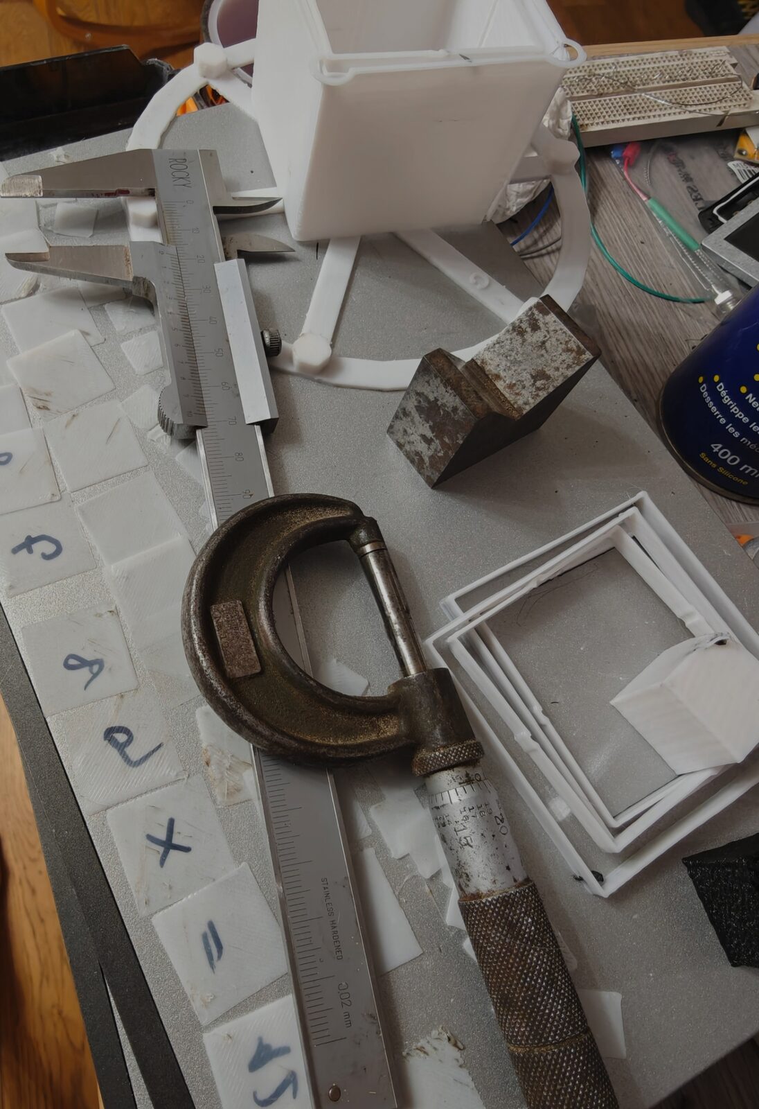
The bench on day three. Everything that served as a judge: the caliper, an old inch micrometer, the 20 mm cube, the first-layer frames, the thickness squares numbered in marker, and behind, the seven-pillar part of the extended calibration.
An “always a bit disappointing” machine
I have an FLSun QQ-S delta printer, bought in January 2020. A delta is that triangular-tower printer where the nozzle hangs from three articulated arms that ride up and down three columns; there are no separate X, Y and Z axes as on a Cartesian printer — the nozzle position is the result of a calculation from the height of the three carriages. It is fast, quiet, elegant, and far more sensitive to geometry errors than a straight-axis machine: an arm one millimetre too long or a column one degree off does not give a simple error but a bowl, a dome or a three-lobed clover that varies across the whole bed.
Rarely used, this machine had always been a bit disappointing. Not catastrophic: parts came out. But the walls lacked strength, dimensions were off by a few tenths, the first layer never stuck everywhere, and above all no setting had a clear effect. I had ended up printing with a bigger nozzle “so it would go faster”, replaced the belts after destroying a set by over-tensioning, and parked the machine next to a Bambu Lab that simply prints right without being asked.
That comparison is what launched the investigation. Not “how do I tune my slicer”, but what exactly does this machine have, and what can be recovered. This post tells three days, 4 to 6 September 2026, carried out with an AI (Claude) that drives the printer, writes the tools and reads the manuals, while I hold the caliper, the sheet of paper and the camera. It also tells a fine methodological mistake, hers and mine, because that is what happens when you search for real.
The setup
The original firmware was going to be replaced by Klipper. Klipper is a 3D printer firmware in two parts: a tiny program on the printer’s board that only drives motors and heaters in real time, and a host program on a computer next to it that does everything else — kinematics, calibrations, macros. You lose the printer’s touch screen (Klipper cannot drive it), you gain calibration tools that exist nowhere else, especially for deltas.
What Klipper brings, concretely, compared with the original Repetier — or a Marlin:
- Offloaded computation. A classic firmware does all the delta kinematics on the board’s small microcontroller, with the approximations that imposes; Klipper does it on the host computer, in floating point, and only sends the board precomputed step times. On a delta, where every move is a square root per column, that shows in movement precision and achievable speed.
- Calibration tools:
DELTA_CALIBRATE, which derives the full geometry from seven points, with or without a probe; the extended arm calibration; the bed mesh; andTUNING_TOWER, which varies a parameter with height during a print, to settle in one part what would take ten tries. - Pressure advance and input shaper, compensation for the pressure in the bowden and for vibrations, which the original firmware lacks and which account for most of the quality gap with a modern machine.
- A plain-text configuration, readable, commentable, versionable, where every value has a provenance; and a local socket through which everything can be driven from a script.
What it does not bring: it does not raise the hotend’s flow ceiling, it does not replace wrong mechanics, and it needs a computer next to the printer.
The host, for now, is my laptop plugged in over USB; a Raspberry Pi will take over. No web interface yet: Klipper exposes a local socket you send commands to, and the AI wrote in an hour what was needed to avoid typing G-code by hand: a client to send a command and read the answer, a print-monitoring script, and above all calib.py, a keyboard driver where one key is one gesture — h to home, s to start the delta calibration, m for the bed grid, d/u to lower or raise the nozzle by 0.1 mm, [/] to adjust the first layer while it prints.
The stance from the start is the same as on the Bambu: we measure, we don’t guess. Every value written into the configuration comes from a measurement on the machine, and every correction is followed by a control part.
Going deeper: what a delta firmware does, and what each setting corrects
On a delta, the nozzle position is computed from seven and a half numbers: the arm length (arm_length), the delta radius (delta_radius, the horizontal distance between a column’s axis and the arm pivot on the carriage, minus the one on the effector side), the angle of each column (nominally 210°, 330° and 90°), and the endstop height of each column (position_endstop, where the carriage triggers its limit switch). When one is wrong, the error on the bed has a recognisable shape:
| Wrong setting | Shape of the error on the bed |
|---|---|
| one endstop height | a tilted plane towards that column |
| delta radius | a centred, symmetric bowl or dome |
| arm length | a bowl/dome too, plus a scale error in XY (parts too big or too small) |
| a column angle | a clover distortion, three lobes, and twisted parts |
Klipper measures them all with DELTA_CALIBRATE: you bring the nozzle down onto seven points of the bed (with a probe, or with paper), and it adjusts the parameters so that those seven points lie in a plane. The extended version (DELTA_ANALYZE) adds measurements of a printed part to adjust the arms one by one. On top of this geometry, the bed mesh corrects what remains — the flatness defects of the glass itself — by interpolating between measured points. Order matters: the grid can only properly correct what is local; a geometry error is not local, and a grid trying to compensate for it never quite gets there. That is the heart of this post.
Mechanics first: the belts
Before touching the firmware, a quick audit of what moves. The belts on this machine have a history: a first set destroyed by over-tensioning (“I had read you should never tension them, and that’s what happened to me”), back when “no setting had any effect”. That sentence, in hindsight, was the signature of a mechanical problem and not a slicer one, and it is what justifies starting there.
The AI first proposed the method you read everywhere: pluck the belt, measure the note with a guitar app, aim for a frequency. Three rounds later, I cut it short: “it’s not a string, if I tension it enough to ring it’ll break everything”. She checked, and I was right: on this machine the free span is 65 cm, the target frequency would be under 30 Hz, where apps drop an octave (I was reading 70 Hz without ever landing on the same value twice). Above all, a Hackaday article reminds us that print quality barely changes with frankly loose belts, as long as the axis does not lag the motor; whereas over-tensioning breaks motor shafts (a NEMA 17 takes 28 N of radial load). There is no trade-off to find: no benefit to tightening, a risk to tightening.
The method kept is the one I have used for years: slacken frankly, then re-tension just to the threshold where the belt starts to vibrate softly instead of flapping. You approach from below, so over-tensioning is impossible; the threshold is exactly the lower limit of no-play; the same gesture on the three columns equalises by construction. The six pulleys spun freely. Audit closed. We will see later that this re-tensioning, done at the wrong moment, still cost dearly.
What the machine had inside
Before flashing, the original firmware’s memory had to be read: the values it used are the starting point of the Klipper configuration, and once flashed, they can no longer be read. First surprise, plugging in the USB: it is not Marlin. Everything you read about the QQ-S assumes Marlin, and the AI had prepared the Marlin commands (M503 to read the configuration, M665/M666 for the delta geometry). The machine’s answer: Unknown command. The firmware announces itself as FIRMWARE_NAME:Robin and it is Repetier, which dumps its memory with M205. First lesson, not the last: verify before asserting.
The dump — 970 m of filament and 233 machine hours — delivered two things.
First the real values: arms 278.6 mm (the reference Klipper config says 280), delta radius 140.8 (the reference says 130 — ten millimetres apart, enough for a monstrous dome had we taken the reference), height 376.03, 100 steps/mm on the columns and 367 steps/mm on the extruder (remember that figure).
Then an observation that already explained a lot: every per-column correction term was at zero. Delta radius A/B/C, diagonal correction A/B/C, all zero. This machine had never been finely calibrated as a delta — or had been at the factory and lost it in a firmware update, which resets the EEPROM: that is my hypothesis, and the EEPROM keeps no history to settle it. Either way, its geometry errors, whatever they were, had been intact for years, and the extruder steps probably came from the same reset.
Going deeper: reading a Repetier EEPROM, and what carries over to Klipper
M205 returns one line per value, in the format EPR:<type> <position> <value> <label>. The firmware replies ok before the answer, not after: a script that reads “until ok” misses everything; you have to read until silence. What carries over to Klipper: Diagonal rod length → arm_length, Horizontal rod radius at 0,0 → delta_radius, Z max length → position_endstop of the three columns, Max printable radius → print_radius, and steps/mm → rotation_distance (for a GT2 belt on a 16-tooth pulley, 32 mm per turn; for the extruder, rotation_distance = steps_per_turn / steps_per_mm, i.e. 3200 / 367 = 8.719). PIDs do not carry over (different scales), they are redone. The per-column endstop offsets (X 0, Y 7, Z 83 steps in the EEPROM) were not carried over: Repetier’s sign convention is not certain, and DELTA_CALIBRATE re-derives them anyway.
The full dump is in the files at the end of the post (README-flsun.md points to the repository’s eeprom-repetier.txt).
Klipper, and motors with no strength left
The flash itself is uneventful: Klipper compiled for the STM32F103 of the MKS Robin Mini board, with a 28 KB bootloader, an 8 MHz crystal and the USART3 serial port; the binary passed through Klipper’s small update_mks_robin.py script that scrambles it into the format the MKS bootloader expects; copied to a 4 GB SD card in FAT32, printer off when inserting. A beep, “complete” in green, and Klipper answers Klipper state: Ready.
And then the first homing failed. No trigger on stepper_b after full movement: a carriage did not reach its switch. The second homing too, on another column. The motors growled, climbed at 5 mm/s, stalled at 25, and came back down “limply”.
What followed is a lesson rather than a story. The AI ran through hypotheses — step pulse duration, microstepping mode, belts, a current potentiometer that does not exist on this board —, each tested, each dismissed, and each test made the conversation longer without adding information. It is a behaviour worth knowing when working with an AI: the more its context window fills with failed attempts, the more it slides towards the next attempt instead of returning to the facts. What stopped it fits in one sentence, a hard constraint: “before the flash, everything worked perfectly”. The day before, under Repetier, the same mechanics worked; the hardware was out of the question by construction, and the only valid question became: what did the old firmware do that the new one does not?
She then did what she should have done first: read this board’s pin file in the Marlin sources, pins_MKS_ROBIN_MINI.h, and look for everything the old firmware initialised at boot. And there:
MOTOR_CURRENT_PWM_XY_PIN  PA6
MOTOR_CURRENT_PWM_Z_PIN   PA7
MOTOR_CURRENT_PWM_E_PIN   PB0
MOTOR_CURRENT_PWM_RANGE   1500
DEFAULT_PWM_MOTOR_CURRENT { 800, 800, 800 }
On the Robin Mini, the reference voltage that sets the motor current is not set by a potentiometer: it is generated by the microcontroller, as a PWM signal on three pins. Repetier set them at boot. Klipper left them floating — near-zero reference, tiny torque, drift over the minutes (“it moves better than at the start”). And the official Klipper configuration for this printer, printer-flsun-qqs-2020.cfg, does not contain these lines (as I write). Anyone following that config on a Robin Mini has under-powered motors.
The fix is three configuration blocks: one hardware PWM output per pin, 800 on a scale of 1500, at 1 kHz, Marlin’s default value. Immediate homing, three columns triggered, normal speed. “Perfect movement!“
Going deeper: the three blocks, and the methodological lesson
[output_pin motor_current_ab]
pin: PA6
pwm: True
hardware_pwm: True
cycle_time: 0.001
scale: 1500
value: 800

[output_pin motor_current_c]
pin: PA7
# same

[output_pin motor_current_e]
pin: PB0
# same
800/1500 corresponds to roughly 1.28 V of reference, about 0.9 A RMS on the board’s TMC2208 drivers. Adjust in steps of 50, not beyond ~1000 without cooling. The three pins are on the same timer (TIM3); hardware_pwm is accepted without error.
The lesson goes beyond this board: when “it worked before” under another firmware, you must inventory everything the old firmware initialised — current, microstepping, driver modes, not just STEP/DIR/ENABLE. The AI’s mistake was not being wrong, but reasoning (“the current comes from a potentiometer, so it hasn’t changed”) instead of checking how this particular board produces its reference.
Calibrating a delta without a probe
The machine’s probe was not around. That does not matter: Klipper’s documentation recommends manual calibration on a delta anyway, because a probe mounted beside the nozzle introduces its own error when the effector tilts. The method is the sheet of paper: DELTA_CALIBRATE METHOD=manual sends the nozzle 2 mm above seven points of the bed, one in the centre and six in a circle; at each point you lower the nozzle in 1 mm steps, then 0.1, then by bisection, until a 0.1 mm sheet of paper just drags between nozzle and glass; you accept, the nozzle goes to the next point. Seven points, a quarter of an hour. Klipper then computes the parameters that put those seven points in a plane.
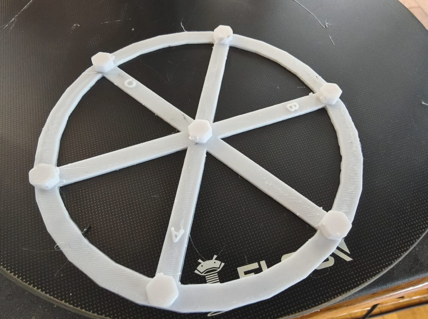
The calibrate_size.stl part shipped with Klipper, for the extended calibration of the arms. It will be printed but not used: we will see why.
The first result, on the afternoon of 4 September: delta radius 141.18 (the EEPROM said 140.8), and above all column A at 211.02° and column B at 330.45°, instead of the nominal 210° and 330°. One degree on A. That is huge for a delta, and it was the defect “no setting corrected”: a wrong column angle twists parts and warps the bed into a clover, and no slicer setting, no bed grid, catches up with that.
Right after, the bed mesh: BED_MESH_CALIBRATE METHOD=manual, same paper gesture on 13 points, to correct what the glass has that isn’t flat. Range 0.51 mm, dominated by the two edges of the Y axis. Saved, loaded at the start of every print. Cold calibration done.
Note this detail: the grid was measured cold, and I re-tensioned the belts between the delta calibration and its verification. We will come back to it.
The extruder was lying by 11.5%
The simplest test in the world, and I had never done it in six years: a marker line on the filament 120 mm from the extruder inlet, ask the machine to feed 100, measure what is left. Expected: 20 mm. Measured: 31.5 mm. The machine had pushed 88.5 mm for 100 requested.
The EEPROM’s 367 steps/mm, faithfully carried into Klipper (rotation_distance 8.719), were wrong by 11.5%. Corrected to 7.716, cross-checked on a second test: 20.0 mm left, “perfect!”.
Measure what that means: every layer this machine ever laid down was missing a tenth of its material. Weak walls, open seams, uneven tops, poor layer adhesion — everything I blamed on “the delta” or “the PETG”. And no slicer setting compensates for an error you don’t know about: you can push flow to 110% at random, you don’t know why, and it doesn’t hold from one filament to the next.
With the column angles and the motor current, that makes three factory defects — from the factory or from a firmware update that reset everything, the machine will not say which — never seen.
PID, wet PETG and the first print
The temperature controls (PID) recalibrate in ten minutes, but the nozzle’s tripped Klipper’s thermal protection: heater extruder not heating at expected rate. The curve showed a perfectly healthy heat-up (27 → 234 °C in 95 s), then an unusual inertia between the block and its thermistor that makes the protection believe heating has stopped. No disabling: a widened window in [verify_heater extruder], documented in the config.
Then the first part, in PETG, the one that had been living on the machine for ages. The cube came out… like this:
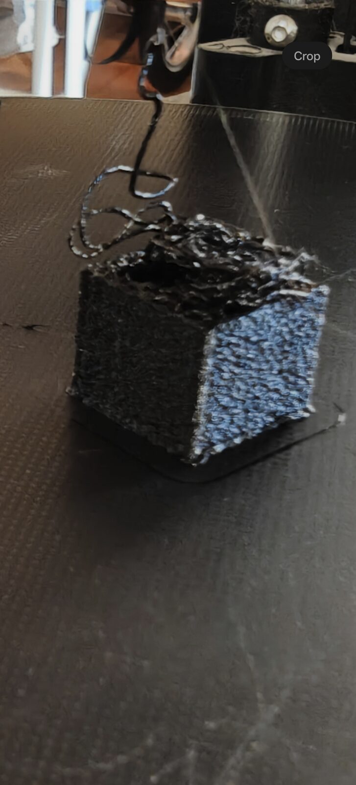
The first cube, in PETG. It crackled in the nozzle while printing: the spool was saturated with water. The walls are foam.
That is not the printer: it is the filament. PETG is hygroscopic, and a spool left in the open for years crackles in the nozzle (the water flashes to steam) and comes out foamy. A good part of this machine’s “disappointing reliability” was that. A new spool of PLA for the whole calibration; the PETG will go through the filament dryer.
In PLA, Klipper’s square.stl (a frame with a one-millimetre wall, five millimetres high, six minutes): wall 1.00 mm, height 5.00. And the first control cube: Z 20.00 · X 20.40 · Y 20.45. The height is perfect — the columns are good. The 2% excess in XY, we will settle at the end.
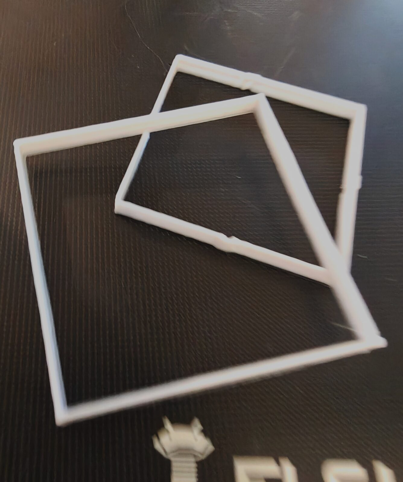
square.stl: Klipper’s first-layer and flow test. Wall 1.00 mm, spot on.
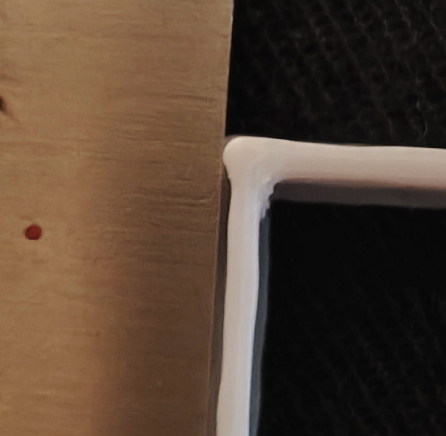
The foot of a frame, very close: the small lip overflowing at the base says the first layer is a little too squished. This is the test used to set the first-layer offset, in 0.05 mm steps, while printing.
Pressure advance
Last setting before tackling the bed: pressure advance. On a bowden machine (the extruder motor is on the frame, a long tube brings the filament to the nozzle), the pressure in the tube takes time to rise and fall; without compensation, corners bulge and line ends ooze. Klipper compensates by pushing a little more before accelerations and pulling back before decelerations, with a single parameter. You measure it with a test tower where the parameter grows with height (TUNING_TOWER), and look by eye for the height where corners are sharpest.
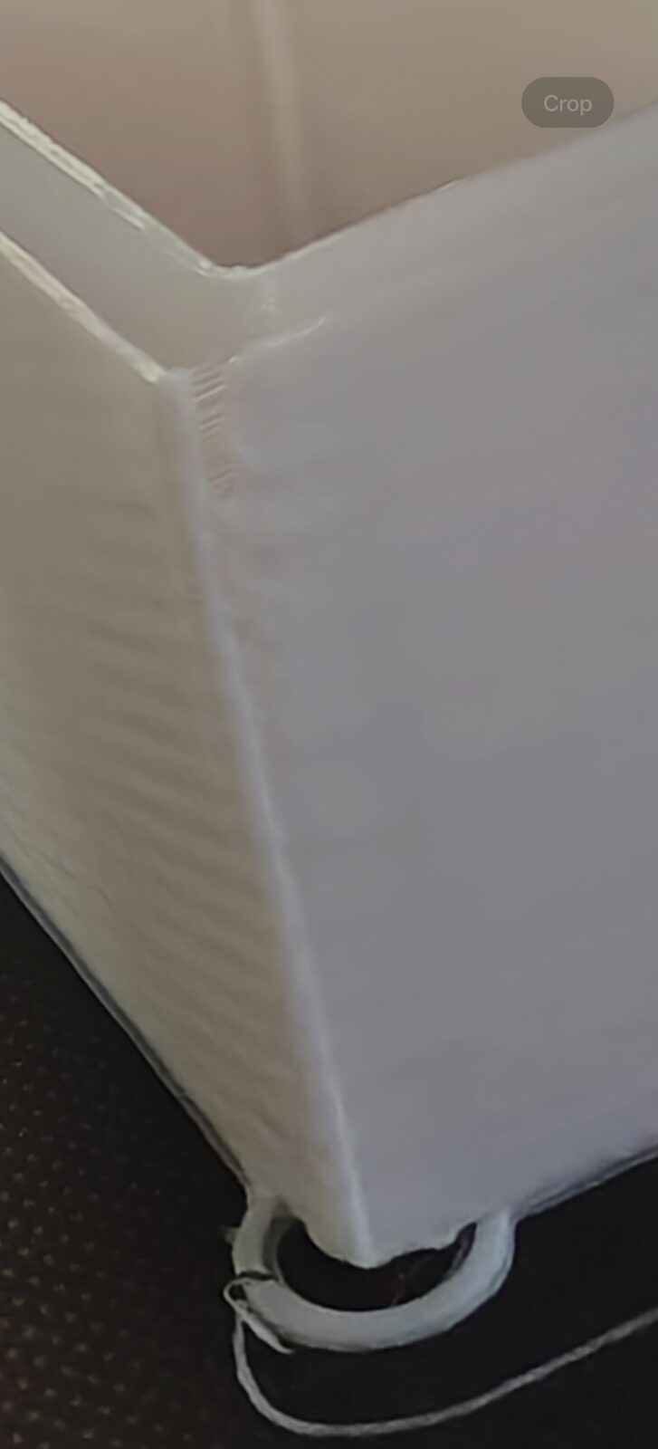
The square_tower.stl tower: at the bottom, not enough compensation, corners bulge; at the top, too much, they hollow. The best corner is at 19 mm.
Best corner at 19 mm, 0.020 per millimetre: pressure advance 0.38, in the expected range for a bowden. Saved.
The spiral, or how to see your first layer
To judge levelling, I needed better than the sheet of paper: I remembered a spiral object you print to see the first layer at a glance. Rather than look for a file sliced for another machine, the AI generated the G-code directly: a single continuous line, an Archimedean spiral, from the centre out to a 120 mm radius, one turn every 2.5 mm, a single 0.2 layer. Twelve minutes. Where the nozzle is too close, the bead is squashed, flat, translucent; where it is too far, it is round, narrow, poorly stuck. On a round bed, it is the most readable test there is.
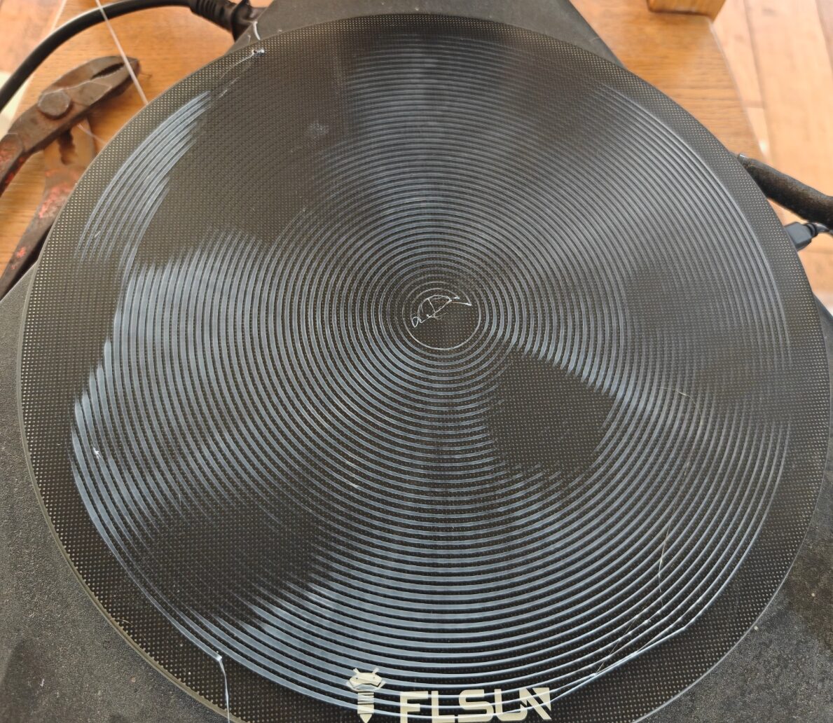
The first spiral. Three bright lobes 120° apart: the signature of a delta geometry, not of a warped bed.
The first spiral showed a three-lobed clover. A warped glass does not make a clover; a badly calibrated delta does. And yet the calibration had just been done. The right conclusion would have been: the geometry isn’t right yet, redo the calibration. We took the other path.
The false trail: two days correcting the grid
My request was reasonable: “a print with a predetermined thickness would be more relevant than the paper test”. The AI built the method: print a one-layer square on each of the 13 grid points, measure their thickness, and correct each grid point by its deviation from the mean. A square thicker than the others = the nozzle was higher there = the bed is lower there than the grid believes = lower the point. She wrote the script (fix-mesh.py) that homes, places the nozzle 100 mm above each square to identify it (“how do I tell which is which?” — the logo is not a reference), records the measurements, rewrites the grid. My micrometer being graduated in inches, you enter thousandths (13t).
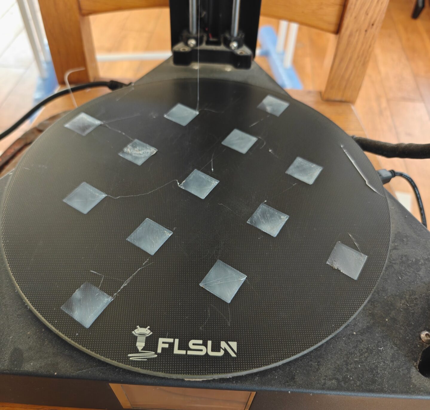
Pass 1: thirteen 20 mm squares, one layer, one per grid point.
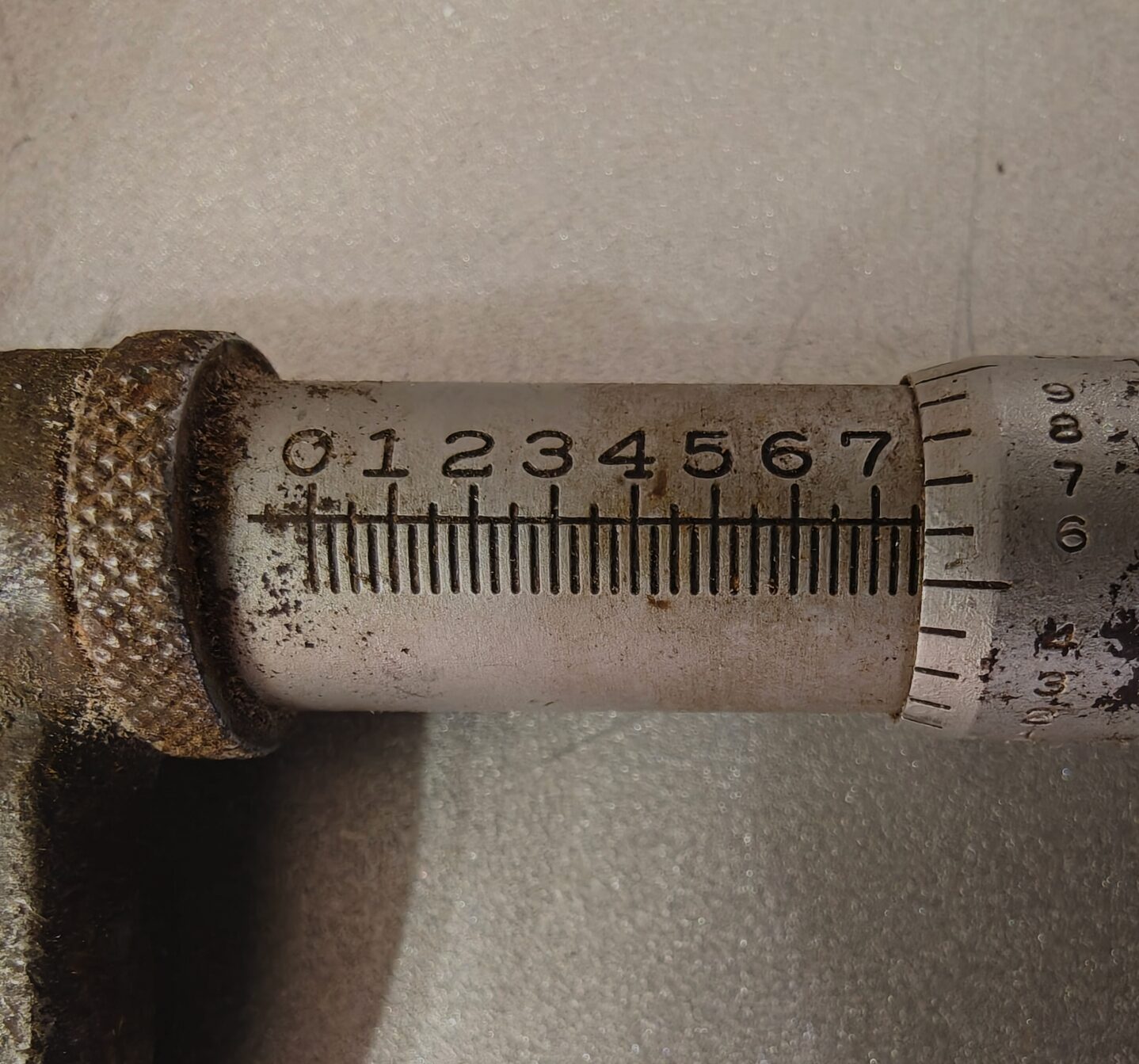
The micrometer, graduated in inches: one sleeve mark is 25 thousandths, the thimble gives the units. 13 thou = 0.33 mm.
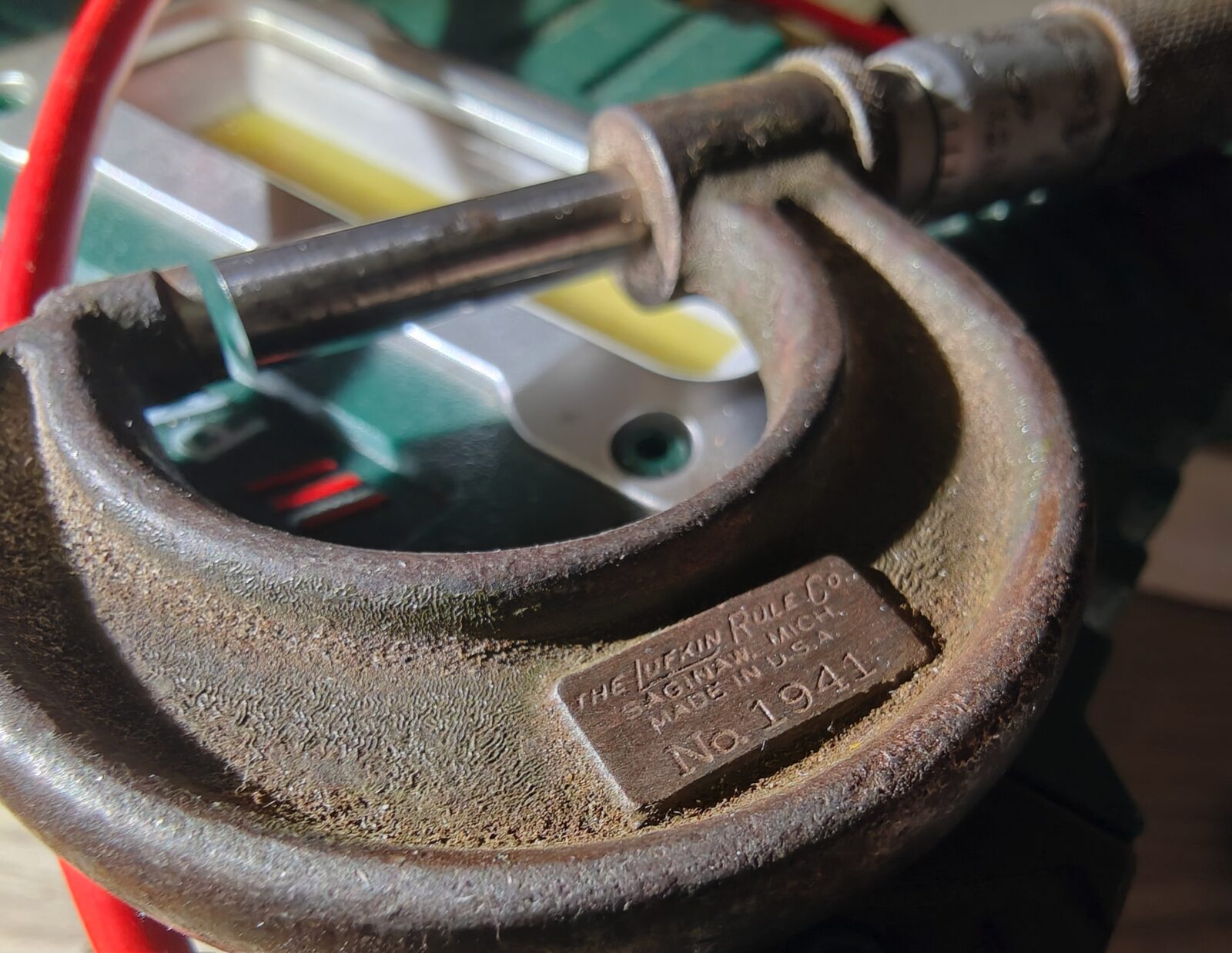
The instrument itself: a Lufkin Rule Co. from Saginaw, Michigan, No. 1941. Older than me, and still measuring to a thousandth of an inch. Between its anvils, one layer of PLA.
It worked. Pass 1: thickness range 0.30 mm. Pass 2: 0.084 mm. The next spiral was clearly better, the clover fading. Then we moved to a finer grid, 7×7 (29 points, 40 mm pitch instead of 55), because the remaining defects seemed to fall between the points. Pass 3, pass 4, reduced gain to avoid oscillating. And on every spiral, the same zones came back, attenuated but in the same place.
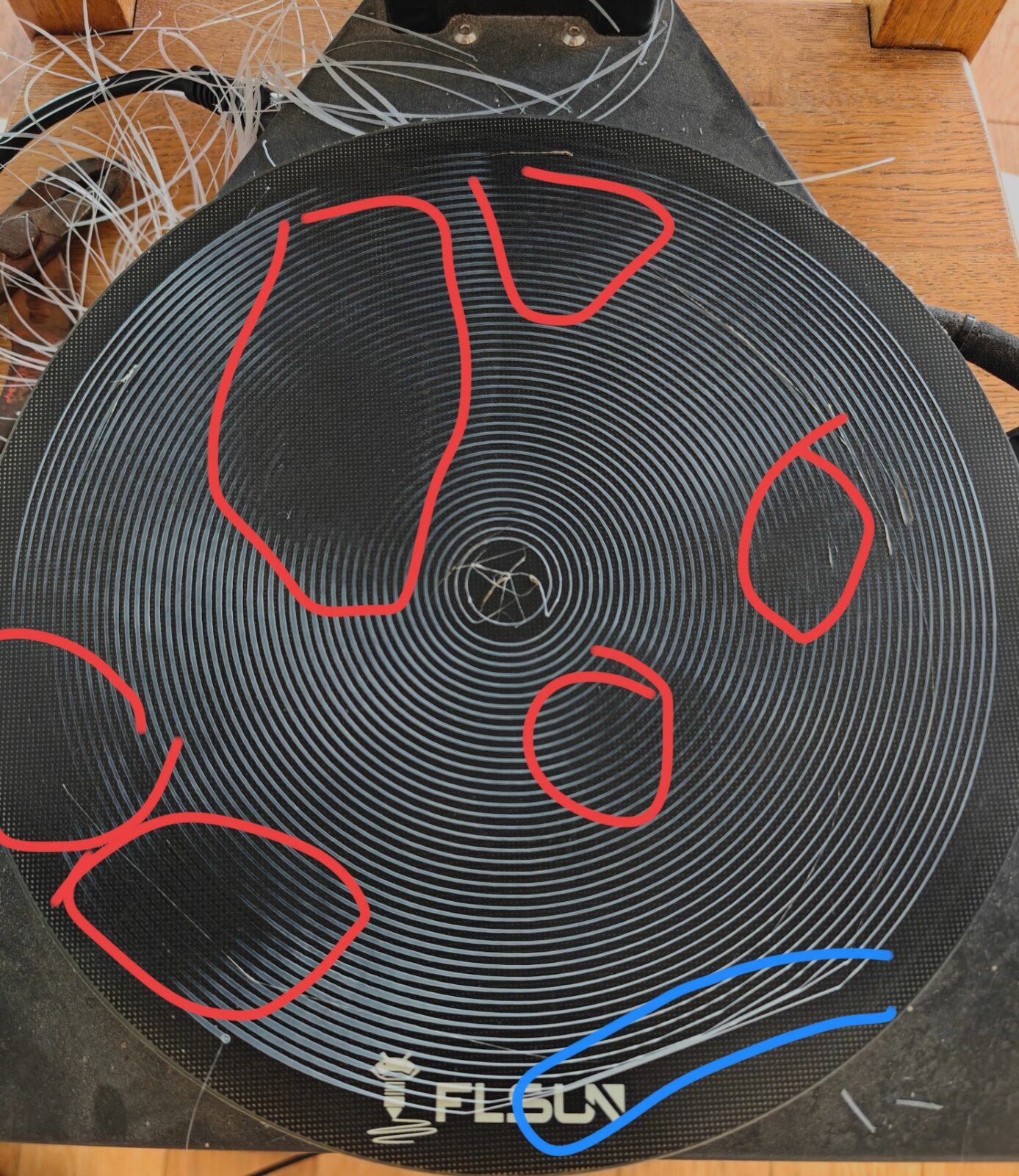
Spiral 3, annotated by me: red = too close (scraped), blue = too far (not stuck). Five patches, no clear clover any more.
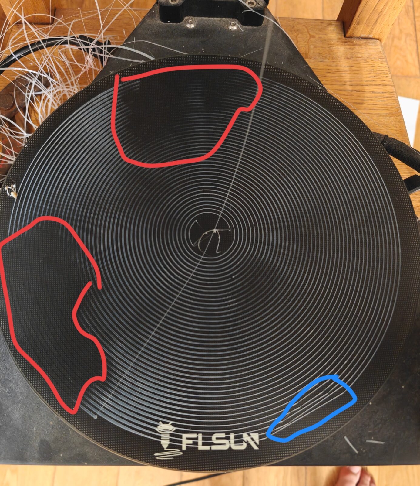
Spiral 4, after the 7×7 grid: two red zones instead of five, the blue still at the same corner.
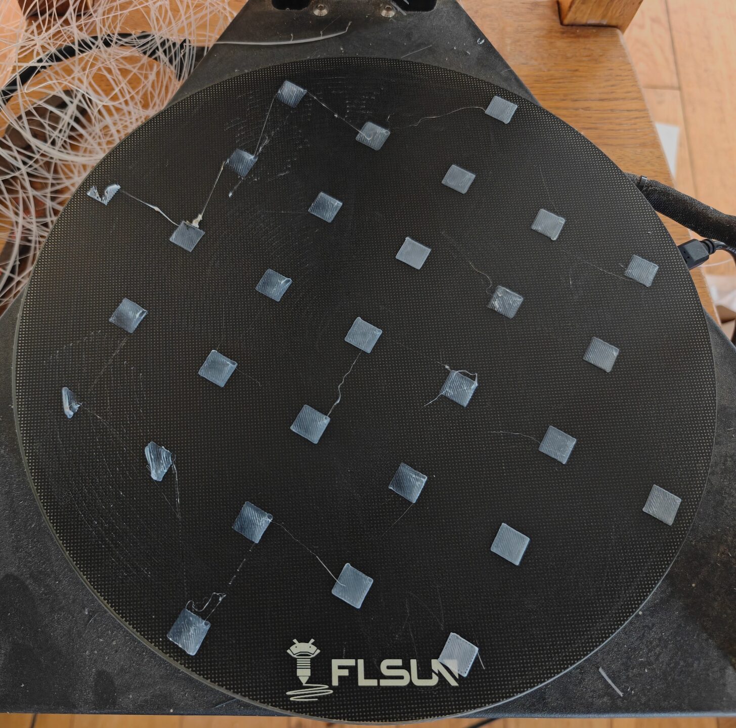
7×7 grid, 29 squares of 10 mm. Two squares on the left are torn: too close. The micrometer, though, measured them “thick”.
That is when I said what had to be said: “to me the error is very repeatable on the last three spirals. We have gaps in the same zones and the corrections have improved things but they don’t really fix the root of the problem.” Three correction passes should have been enough. Something independent of the setting was resisting.
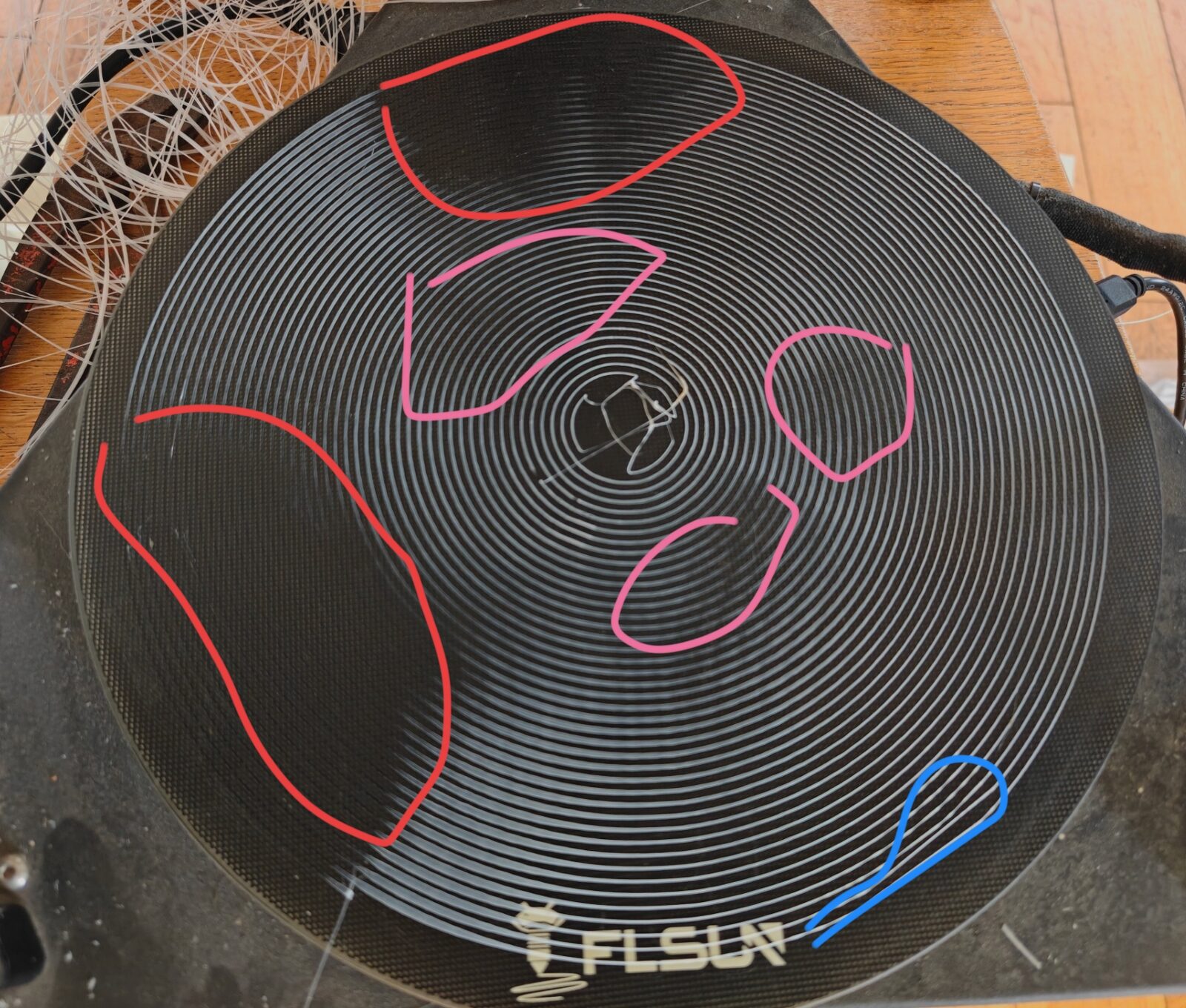
Spiral 5: red, almost no filament; pink, slight lack; blue, not stuck. The same zones, again.
Two macro shots settled it. In the blue zone, the bead is round, narrow, laid down without being pressed, and the transition is gradual over 25 mm towards the edge: the nozzle moves away steadily going outwards. In the red zone, the beads are wide, flat, translucent, squashed to a film — you can see the bed’s dots through them. Too close, really.
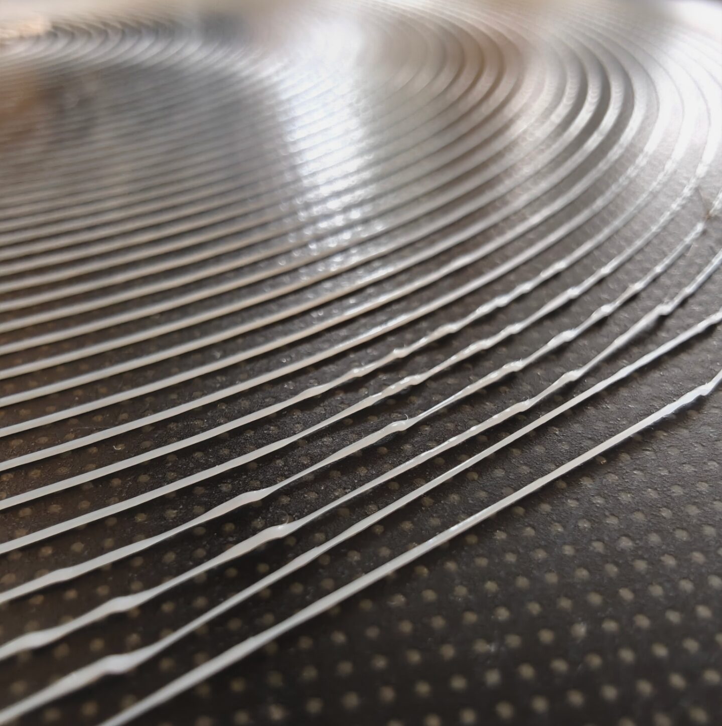
Blue zone: round bead, not pressed, wavy and knotted where it caught. Too far.
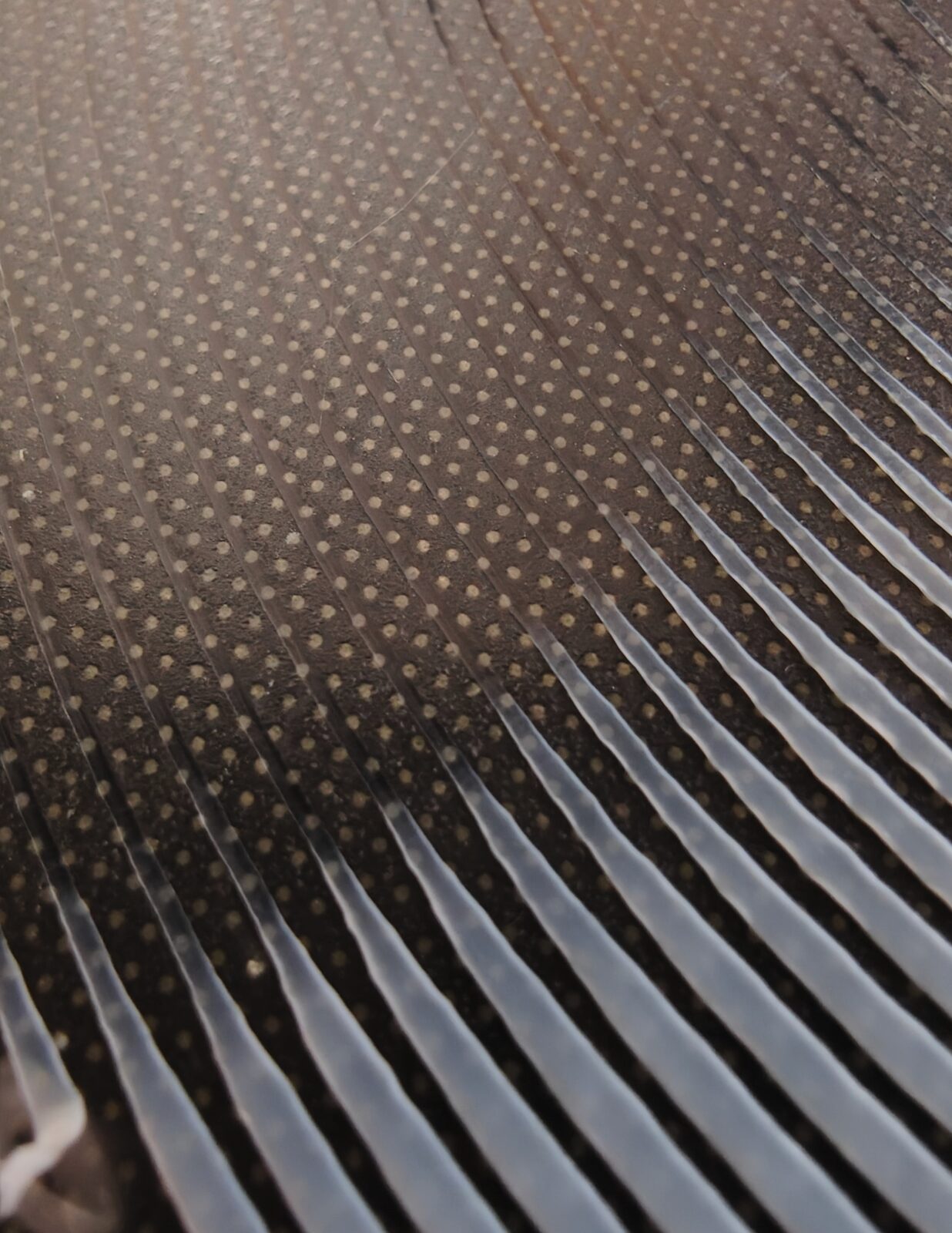
Red zone: squashed, translucent beads, the bed shows through. Too close, no argument.
And here is the contradiction: in those red zones, the squares measured a normal thickness. The explanation, once you see it: a square printed too close grows a raised lip around its edge, and the micrometer’s anvils, six millimetres across, land on that lip. It reads “thick” exactly where it is squashed. The squares method was biased in precisely the direction that prevented convergence. Two of the AI’s conclusions built on those measurements (“the nozzle is 0.4 mm from the glass on average”, “the global zero must come down”) fell with it.
The root question remained: why such repeatable zones? My lead was the belts. The AI wrote a repeatability test (key R: same point, five approaches along different paths, sheet of paper): repeatable to 0.1 mm whatever the path. Belts and play out of the question. But that test gave something else: at those points, the paper dragged at Z = +0.2 and +0.6 mm — the machine believed the bed was half a millimetre lower than it is. And the grid itself carried a 0.65 mm front-to-back slope that nothing justifies on a calibrated delta.
The cause was in day one’s sequence. The delta calibration had been done cold; between that calibration and its verification, I had re-tensioned the belts; the verification had shown an offset, and the AI had applied +0.4 mm uniformly to the three endstops. But the re-tensioning had shifted the three columns unequally. The residue, a tilted slope, went into the grid, and a delta grid never makes a slope flat: it leaves lobes, which four passes of micrometer squares chased without catching.
Going deeper: why a grid does not compensate a geometry error
An endstop error on one column does not produce an exact tilted plane but a slightly curved surface, because the effector’s tilt changes with its position; an angle error produces a clover. The grid samples that surface at 13 or 29 points and interpolates (here bicubic) between them: it captures the trend, not the fine curvature, and leaves a residue wherever the true surface departs from the interpolation. The bigger the geometry error, the bigger the residue. That is why Klipper asks for geometry first, grid second, and why “redo the grid” never replaces “redo the delta calibration”. And that is why you must calibrate in the state you print in: a bed at 60 °C is not exactly where it is at 20 °C (here, +0.36 mm at the centre), and the difference is not necessarily uniform.
The arrival: redo everything hot, with paper
Bed at 60 °C, nozzle cold, grid cleared. Manual DELTA_CALIBRATE, seven points with paper, fifteen minutes. The verdict is in the endstops:
| Column | Endstop before | Endstop after | Difference |
|---|---|---|---|
| A | 376.252 | 376.075 | −0.18 |
| B | 376.533 | 375.970 | −0.56 |
| C | 377.204 | 376.859 | −0.35 |
The angles barely moved (A 211.02 → 210.93, B 330.45 → 330.33), the radius neither (141.18 → 141.29). The geometry held. What was wrong were the endstops, unequally: 0.38 mm between A and B. Exactly the slope the grid carried.
Save, home, then the paper grid on the 29 points, half an hour. Centre flat to ±0.1 mm over an 80 mm radius; the front edge dips 0.6 mm at 120 mm from the centre — that is the glass itself, or the delta at the end of its reach, and this time it is measured directly and the grid knows it. Then the spiral:
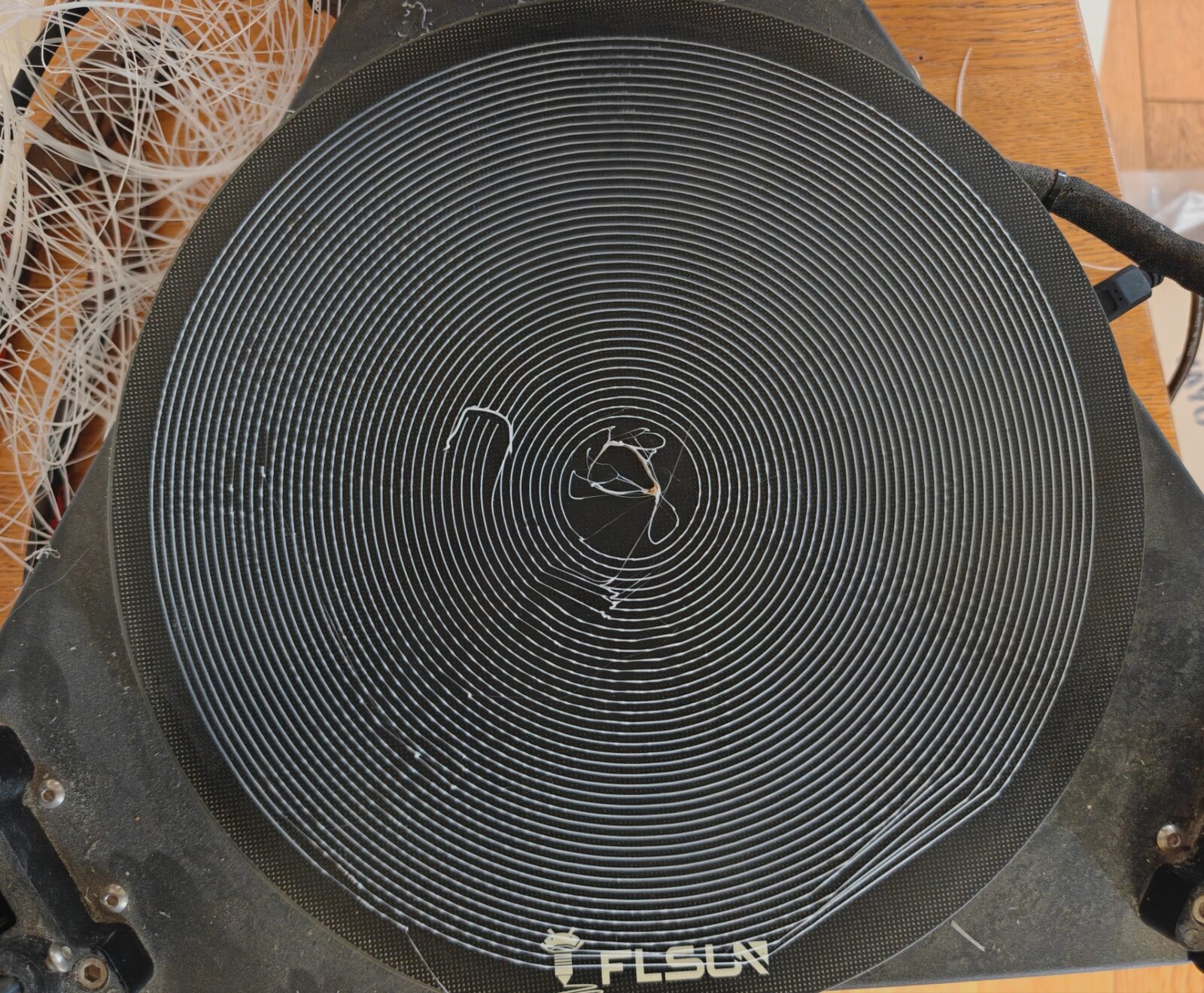
Spiral 6, the first with a consistent geometry and grid, both measured hot. Uniform from edge to edge, front edge included.
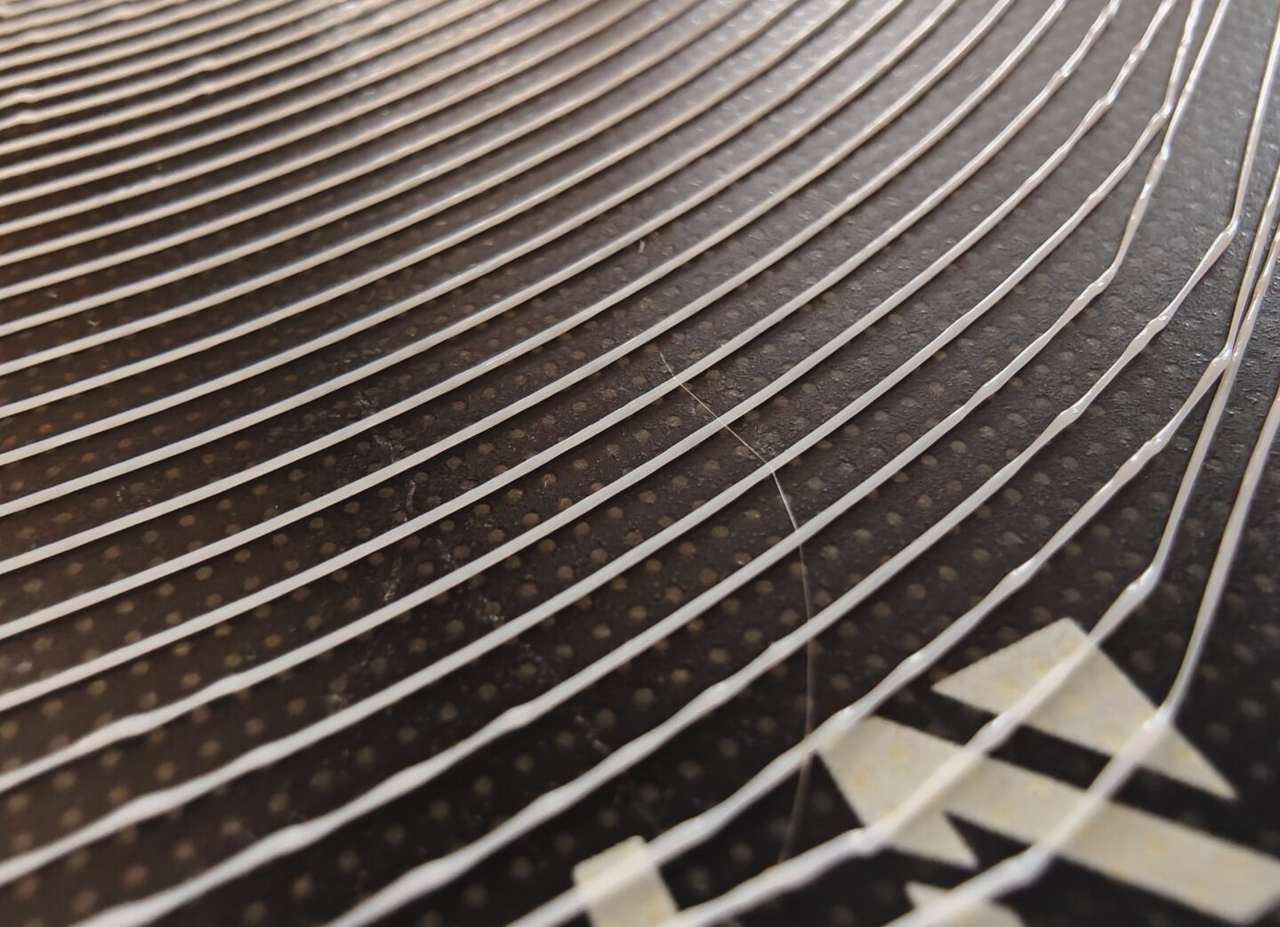
The bead, under the loupe: regular, same width from turn to turn, stuck everywhere.
Six spirals, and the good one was the one where we stopped correcting and recalibrated, in thirty-five minutes, with a single method.
One last trap remained, from the same family: the first-layer offset, +0.07 mm, had been set on day one on the cold zero. On the new, hot zero, the control cube did not stick. A new zero means re-setting the first-layer offset, never carrying the old one over. Test frame, live adjustment in 0.05 steps: −0.10 barely sticks, −0.20 sticks with a 0.3 mm lip at the foot; saved at −0.15.
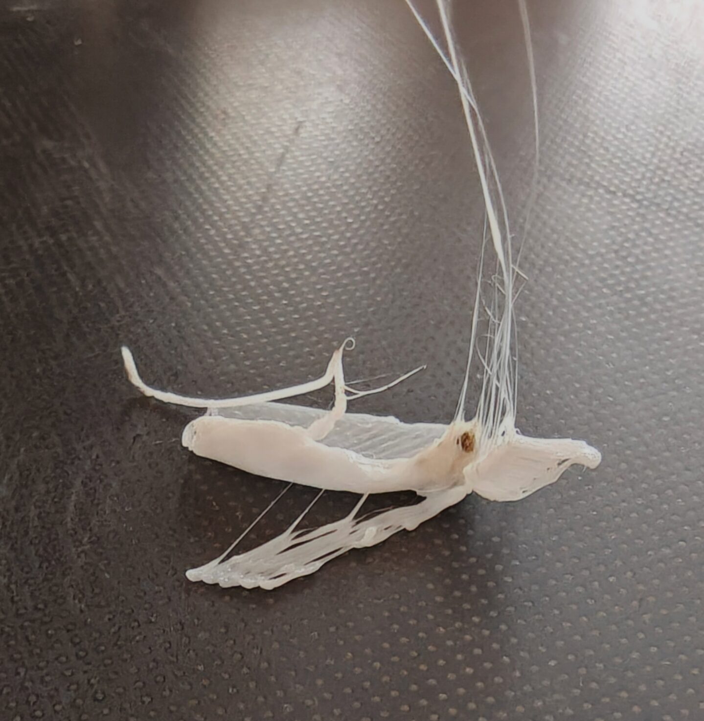
The control cube restarted with the old first-layer offset: it did not stick. The zero had changed, the offset had not.
And the cube, at last: 20.3 × 20.4 × 20.00, a 0.1 mm lip per side. On day one it was 20.40 × 20.45 × 20.00. The XY excess did not move with the geometry, because it is not geometry: the seven-pillar part, measured with the caliper, gave a pillar spacing of 65.0 ± 0.4 mm on a nominal 65, i.e. a scale correct to 0.5%; an arm error would have given +1.3 mm there. What remains is a constant excess of bead width — bulging corners, a 1.07 wall for 1.00 — and that is settled in slicing as on any machine: extrusion multiplier 0.95, XY compensation −0.1 mm, elephant-foot compensation 0.1 mm, in a production profile separate from the raw test profile. The long, delicate extended arm calibration was not necessary. Control cube with that profile: 20.0 × 20.1 × 20.0.
What I take away
Calibrate in the state you print in. Hot. A machine calibrated cold describes a bed that no longer exists when the PLA arrives.
One measurement method, from start to finish. Paper for the geometry, paper for the grid, the test frame for the first layer. Every change of method introduced a bias nobody saw.
Geometry first, grid second, never the reverse. A grid that fails to converge in two passes is not short of points: it is compensating an error that is not its own. And any belt re-tensioning puts the geometry back in play — redo s then m, no shortcut.
When two measurements disagree, go and look. The loupe on the bead settled in one minute what four micrometer passes had not. A measurement is not a truth, it is an instrument with blind spots.
The AI over-engineers when it misunderstands. The grid-correction script with micrometer squares was clever, well made, persistent, with resume and corrections — and it was optimising a bad idea. I am the one who said “it’s repeatable, it’s not the setting”, and the macro shot is what settled it. On the other hand, she found in one reading what six years of forums had not: the PWM motor current, the extruder off by 11.5%, the calibration never done.
“It worked before” is data. Twice in this story, my judgement about my machine was worth more than a method read elsewhere: on belt tension, on homing. And twice, the AI ended up verifying it and proving me right, with sources. That is the right split: she reads fast, she does not measure in my place.
Where things stand
Status on 6 September 2026: machine calibration complete. Geometry, zero and grid measured hot with paper; first layer at −0.15; extruder at 7.716; pressure advance 0.38; PIDs redone; motor current set. Uniform spiral; control cube at 20.0 × 20.1 × 20.0 with the production profile. Remaining, in order of interest: resonance compensation (input shaper) with Klipper’s test tower, a dual-drive extruder in stock, and the Raspberry Pi as host to make the printer standalone. The PETG is drying.
To reproduce
Hardware: a 2020 FLSun QQ-S (MKS Robin Mini board) — the approach applies to any delta, the pins do not; a Linux computer with a USB port; an SD card ≤ 8 GB in FAT32; a sheet of 80 g paper; a caliper; a dry spool of PLA. No probe, no accelerometer.
Before flashing, read the original firmware’s memory (on Repetier: M205; on Marlin: M503) and keep the dump. Note in particular the arm length, the delta radius, the height, and the extruder’s steps/mm.
Firmware: Klipper, make menuconfig → STM32F103, 28 KiB bootloader, 8 MHz crystal, USART3 (PB11/PB10), 250000 baud; then scripts/update_mks_robin.py out/klipper.bin Robin_mini.bin; the file at the root of the SD card, printer off when inserting, power on, wait for “complete”. The bootloader renames the file to .CUR. The build-firmware.sh script does all of it.
Configuration: printer.cfg, with its real values and comments. The three [output_pin motor_current_*] blocks are indispensable on a Robin Mini. The SAVE_CONFIG block at the end of the file holds the calibration results; to start from scratch, delete it and put the EEPROM values back into [stepper_a/b/c] and [printer].
Tools: start-klipper.sh (start the host), send-gcode.sh and klippy-client.py (send a command), calib.py (keyboard driver for calibrations), watch-print.py (print monitoring), make-spiral.py (the spiral). The command-line PrusaSlicer profiles are in slicer/: qqs-pla.ini raw for tests, qqs-pla-prod.ini for parts.
In order, hot (bed at printing temperature, nozzle cold for the paper):
| Step | Command / key | Time | What you get |
|---|---|---|---|
| 1. Homing | h |
1 min | known position |
| 2. Geometry | s (manual DELTA_CALIBRATE), 7 points with paper, then c c |
15 min | radius, angles, endstops |
| 3. Verification | v (7 points at Z = 0.1) |
5 min | ±0.05 expected; otherwise redo 2 |
| 4. Grid | m (manual BED_MESH_CALIBRATE), then c c |
20–30 min | default profile, loaded by START_PRINT |
| 5. Extruder | mark at 120 mm, M83 G1 E100 F60, measure |
5 min | rotation_distance × extruded/100 |
| 6. PID | PID_CALIBRATE HEATER=extruder TARGET=210, same for heater_bed |
15 min | gains, SAVE_CONFIG |
| 7. First layer | square.stl, [ ] live, save in START_PRINT |
7 min | offset |
| 8. Pressure advance | square_tower.stl + TUNING_TOWER … START=0 FACTOR=.020 |
50 min | height of best corner × 0.020 |
| 9. Control | spiral, then 20 mm cube | 12 + 19 min | uniform; 20.00 in Z |
Three rules, if you go for it: hot, a single measurement method, and any mechanical intervention (belts, arms, bed) sends you back to step 2. If a grid does not converge in two passes, do not add points: redo the geometry.
Reading the spiral: red = too close (flat, translucent, scraped bead), blue = too far (round, poorly stuck bead). A three-lobed clover = geometry; local patches = bed or grid; an edge dipping gradually = the glass or the delta at the end of its reach. When in doubt, the loupe.
Frequently asked questions
Do you need a probe to calibrate a delta under Klipper?
No. Klipper’s documentation recommends manual paper calibration on deltas, because a probe offset from the nozzle introduces its own error when the effector tilts. Seven points for the geometry, thirteen to twenty-nine for the grid, half an hour in all.
My motors growl and homing fails after switching to Klipper on an MKS Robin Mini. Why?
Because the motor current is set by PWM from the microcontroller (pins PA6, PA7, PB0) and the official Klipper config for the QQ-S does not do it. Three [output_pin] blocks in hardware PWM, value 800 out of 1500, fix the problem. See Klipper, and motors with no strength left.
Is my FLSun QQ-S running Marlin?
Not the 2020 QQ-S: it runs Repetier (FIRMWARE_NAME:Robin). M503, M665, M666, M900 answer Unknown command; M205 reads the memory. Marlin tutorials do not apply.
My bed grid does not converge, even after several passes. Do I need more points?
Almost never. A grid that does not converge is usually compensating a geometry error (unequal endstops, column angle) or a calibration done cold. Redo DELTA_CALIBRATE hot, then the grid, with the same measurement method.
How do I know whether my extruder pushes the right amount?
A mark on the filament 120 mm from the extruder inlet, M83 then G1 E100 F60, measure what is left: 20 mm expected. Here 31.5 were left: 11.5% under-extrusion since forever. New rotation_distance = old × extruded / 100.
Is the micrometer thickness-squares method any good?
It is biased where the nozzle is too close: the squashed square grows a raised lip around its edge, and the micrometer reads it “thick”. If you insist, 20 mm squares measured at the centre, anvils away from the edge. The spiral and the paper are more reliable.
Should a delta’s belts be tensioned to a precise frequency?
No. The frequency depends on the span length, the mass and the composition of the belt; the same note does not mean the same tension from one machine to another, and on a QQ-S the span is too long to measure. Slacken, then re-tension to the threshold where the belt vibrates softly instead of flapping, on the three columns. And redo the delta calibration afterwards.
The cube is 20.3 instead of 20.00 in XY: should I calibrate the arms?
Not if the excess is constant. Check on a larger part (Klipper’s seven-pillar part, 65 mm spacing): if the scale is right, the excess comes from bead width and is corrected in the slicer (extrusion multiplier, XY compensation). Arm calibration corrects a scale error, not a constant excess.
What did the AI do exactly, and what did the human do?
Claude read the EEPROM and the board’s pin file, compiled and prepared the firmware, wrote the configuration and all the scripts, generated the spiral, ran the calibrations and wrote this post with me. She was wrong about the firmware (Marlin), about the cause of the homing failure (several hours), about belt tension, and about the squares method. I held the sheet of paper, the caliper, the micrometer and the camera; I read the spirals; I said “it worked before”, “it’s not a string” and “it’s repeatable, it’s not the setting”. All three times, that was the right lead.
Short glossary
- Delta: a printer where the nozzle is carried by three articulated arms on three vertical carriages; the position is computed, not measured axis by axis.
- Effector: the central part carrying the nozzle, at the end of the arms.
- Arms (
arm_length), delta radius (delta_radius), column angle, endstop (position_endstop): the geometry parameters; see the box “what each setting corrects”. - Homing: sending the carriages up to their switches, to know their position.
- Bed mesh: a map of bed heights, measured at a few points, that the firmware interpolates to correct the nozzle continuously.
- Paper test: lowering the nozzle until a 0.1 mm sheet just drags; Z = 0 is then 0.1 mm above the glass.
- First-layer offset: a small Z shift applied at the start of each print to adjust how much the first layer is squished.
- Rotation distance: under Klipper, the distance travelled (or filament pushed) per motor turn; replaces steps/mm.
- Pressure advance: compensation for pressure in the bowden tube, which cleans up corners.
- PID: the temperature control; recalibrated with
PID_CALIBRATE. - Bowden: a layout where the extruder motor is on the frame and pushes the filament through a long tube to the nozzle; light for the effector, but elastic.
- Thou: a thousandth of an inch, 0.0254 mm. Old micrometers are graduated that way.
- Lip / elephant foot: a bulge at the base of a part, sign of an over-squished first layer.
- PWM: a square wave whose width is modulated; used here to manufacture a reference voltage for the motor current.
- EEPROM: the original firmware’s memory where it keeps its settings.
References and local copies
So that this post stays useful once links have vanished, the project files are hosted here.
- Klipper documentation: Delta Calibrate · Bed Mesh · Bed Level · Manual Level · Pressure Advance · Resonance Compensation · Config Reference. The test parts (
square.stl,square_tower.stl,calibrate_size.stl,ringing_tower.stl) are in the repository’sdocs/prints/. - Reference Klipper config for the QQ-S 2020 —
printer-flsun-qqs-2020.cfg(without the motor current outputs, as of 6 September 2026). - MKS Robin Mini pinout in Marlin —
pins_MKS_ROBIN_MINI.h(source of the PWM current pins). - Hackaday, “Don’t Tune Your 3D Printer To Middle ‘C’ After All” — on belt tension by frequency (site search).
- PrusaSlicer 2.8.1, the last version with a Linux AppImage — releases. Run from the command line without a display (
env -u DISPLAY); it adds its own heating commands unless it finds realM104/M140in the start G-code. - The project files:
printer.cfg·calib.py·klippy-client.py·send-gcode.sh·start-klipper.sh·watch-print.py·build-firmware.sh·make-spiral.py·slicer/profiles ·README-flsun.md(the machine’s state and the repository’s user guide, in French). - For the record, the false trail:
fix-mesh.py,mesh-to-7.py,first_layer_29.stl, andanalyze-delta.pyfor the extended arm calibration, should it ever become necessary.
Photos and measurements: mine. Firmware, configuration, scripts and writing: with Claude. This post is also available as raw Markdown.