A broken spoke on my hub motor, and the tension meter I ended up welding
Why an off-the-shelf tension meter says almost nothing about a 2.6 mm spoke, and how a torque wrench, two skate bearings and a caliper get the job done
Two minutes, if you keep breaking spokes on a hub motor
- The symptom: a broken spoke on a 2,000 W hub motor, after a first wheel already lost the same way. Thirty-six short, thick spokes, 160 mm long and 2.6 mm thick, whose tension nobody knows.
- Why not a shop tension meter: on a spoke this short and this thick, a device that bends the spoke over 60 mm mostly measures the spoke’s own stiffness, not its tension. And the paper table stops before the useful range anyway.
- The tool: three-point bending over 125 mm, almost the whole free length of the spoke. The force comes from the click of a torque wrench, so it is the same every time. Two skate bearings hold the spoke without friction, a caliper reads the deflection and keeps the maximum when the click releases the load.
- First numbers: at 5 Nm, 100 N of tension move the caliper by 0.07 mm. The wrench’s scatter is worth 8 % of tension. The first spoke measured comes out around 850 N. And a mechanics lesson on the way: a mounted spoke is four times stiffer in bending than a free one, because its ends are held.
- Next: ten readings on the same spoke for the real scatter, a calibration bench, then a map of all thirty-six spokes. That is the next step.
Act I: the spoke that breaks
A 2,000 W hub motor is a hub twenty-one centimetres across, laced into a rim with short, thick spokes: 160 mm overall, 2.6 mm in diameter, thirty-six of them, crossed once. When one of them breaks, it is never a surprise for the wheel, only for the rider. This was my second wheel: the first had ended the same way, one spoke, then two, then a rim going out of true beyond recovery.
A spoke almost never breaks because it is too tight. It breaks because it is not tight enough: at every turn of the wheel, when it passes the bottom, the load slackens it, and a spoke that slackens and tightens thousands of times per kilometre ends in fatigue, most often at the elbow, in the flange hole. So the right answer is not to replace the broken spoke; it is to know the tension of the other thirty-five, and to bring them all to the same level, the right one.
The trouble is that nobody could give me that level. Equalising by ear, plucking the spokes, is an old method that works for equalising but says nothing about the absolute value: a whole wheel too tight rings just as nicely as a whole wheel too loose, and on e-bike forums, rims cracked by excess tension are as common as spokes broken for lack of it. I needed a measurement.
Act II: why not a shop tension meter
A classic bicycle tension meter, the 18-euro model as much as the 80-euro one, works by bending the spoke between two supports about sixty millimetres apart with a calibrated spring, and a table converts the deflection into tension. It works well on a 2 mm bicycle spoke 280 mm long, because that spoke, left to itself, hardly resists bending at all: what the device measures really is the tension that stiffens it.
On my 2.6 mm spoke, it is another story. The bending stiffness of a rod grows with the fourth power of its diameter: going from 2 to 2.6 mm nearly triples it. Over a 60 mm span, the share of tension in what the device reads drops below half; the rest is the spoke defending itself, tension or not. And the paper table of these devices stops before 2.6 mm anyway. I would have had a number, but not a measurement.
The solution comes down to two ideas. First, bend over as long a span as possible, because the share of tension grows with the span: over 125 mm instead of 60, it goes from 45 % to over 70 % for a free spoke. Second, replace the spring with a truly repeatable force. I had a 3 to 20 Nm click torque wrench in a drawer. A click is a known torque, the same every time, to within 4 %. With a lever, it is a known force.
Act III: the design, and its dead ends
The principle stayed the same from the first sketch to the welded tool: three contact points on the spoke, two on one side at the ends of the span, one in the middle on the other side, carried by an arm that the wrench rotates about a pivot. The wrench clicks, the arm has pushed the spoke with a fixed force, and the deflection it took depends on its tension.
What changed was every detail, and I worked them out on a parametric 3D model, with an AI assistant keeping the model, opening it in Blender and running the numbers at each iteration. A few dead ends are worth telling, because they are instructive.
The first version was 3D printed in plastic. The calculation killed it before printing: for 1.5 mm of deflection to measure on the spoke, the PLA arm itself bent by 2.5 mm. The whole load path went to steel.
The second bent the spoke out of the wheel plane, outwards, because it was easier to build. I refused it: a spoke works in the plane of the wheel when the motor pushes, and I wanted to measure it that way. For a round spoke the two are equivalent, but it was not natural, and the pivot would have landed somewhere impossible once the tool sat on a real wheel, with the neighbouring spokes passing 24 mm away.
The supports are bearings, not pins. The literature on tension meters is clear: friction of the spoke on its supports distorts the reading, and by a lot. Two skate bearings, 22 mm outside diameter, 8 mm bore, cost next to nothing and roll without friction. The third point is a plain fork, because it does not move.
The click releases the load. It jumped out at me while animating the mechanism in Blender: a click wrench takes about three degrees of play at the moment it trips, and the torque drops. The spoke only needs two degrees of the arm to spring back. Reading the arm’s position after the click would read nothing useful. Hence a retained-maximum reading: the depth rod of a caliper, pushed by the arm, stays where the arm brought it when the arm backs off. You read the maximum, the one at the click.
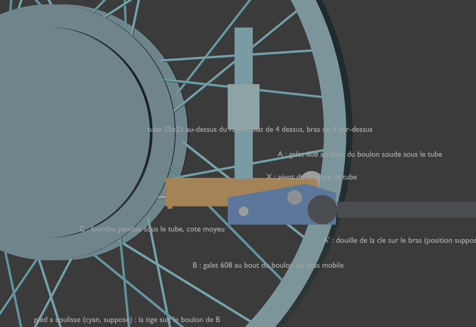
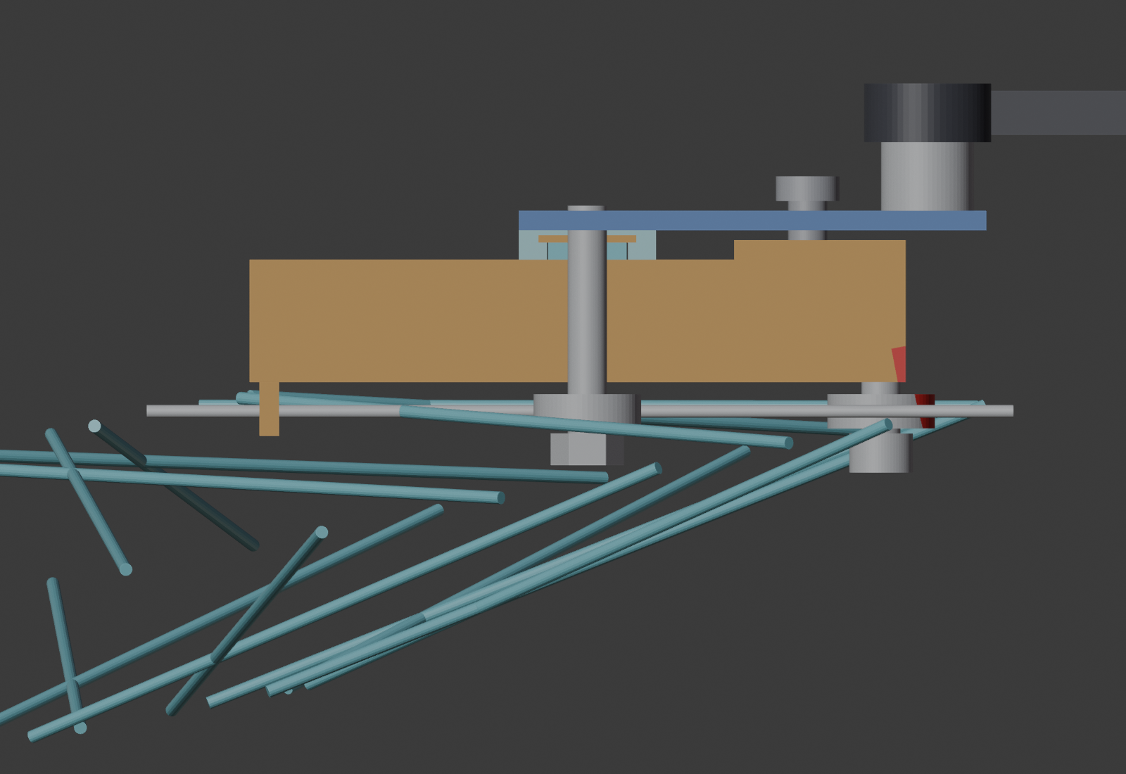
Act IV: the welded tool
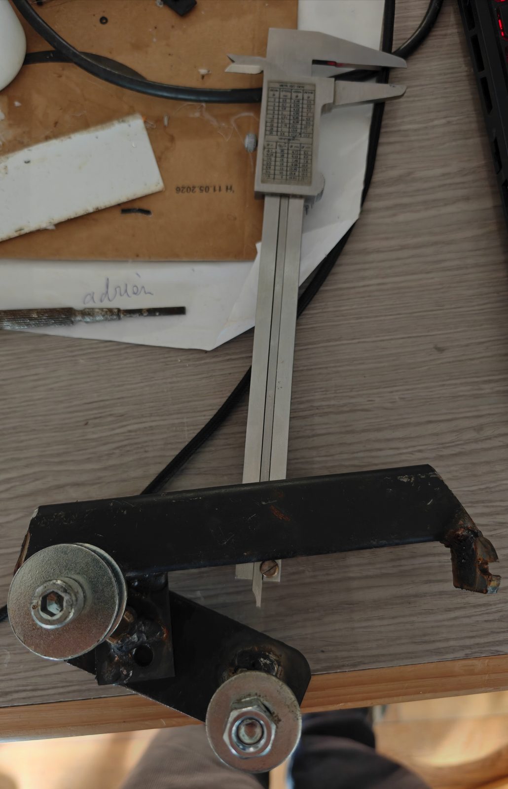
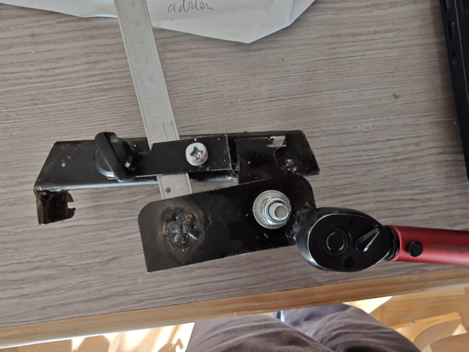
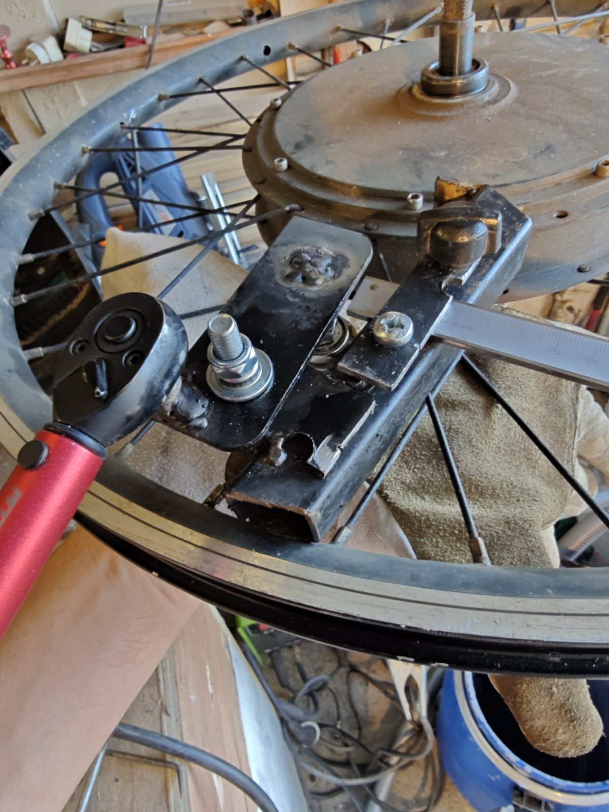
Between the model and the workshop the tool changed again, as it always does when you have steel flats, a welder and a box of bolts at hand rather than the model’s exact inventory. The 3D model was then refitted to the real tool, dimension by dimension, photos in hand. Here is what exists.
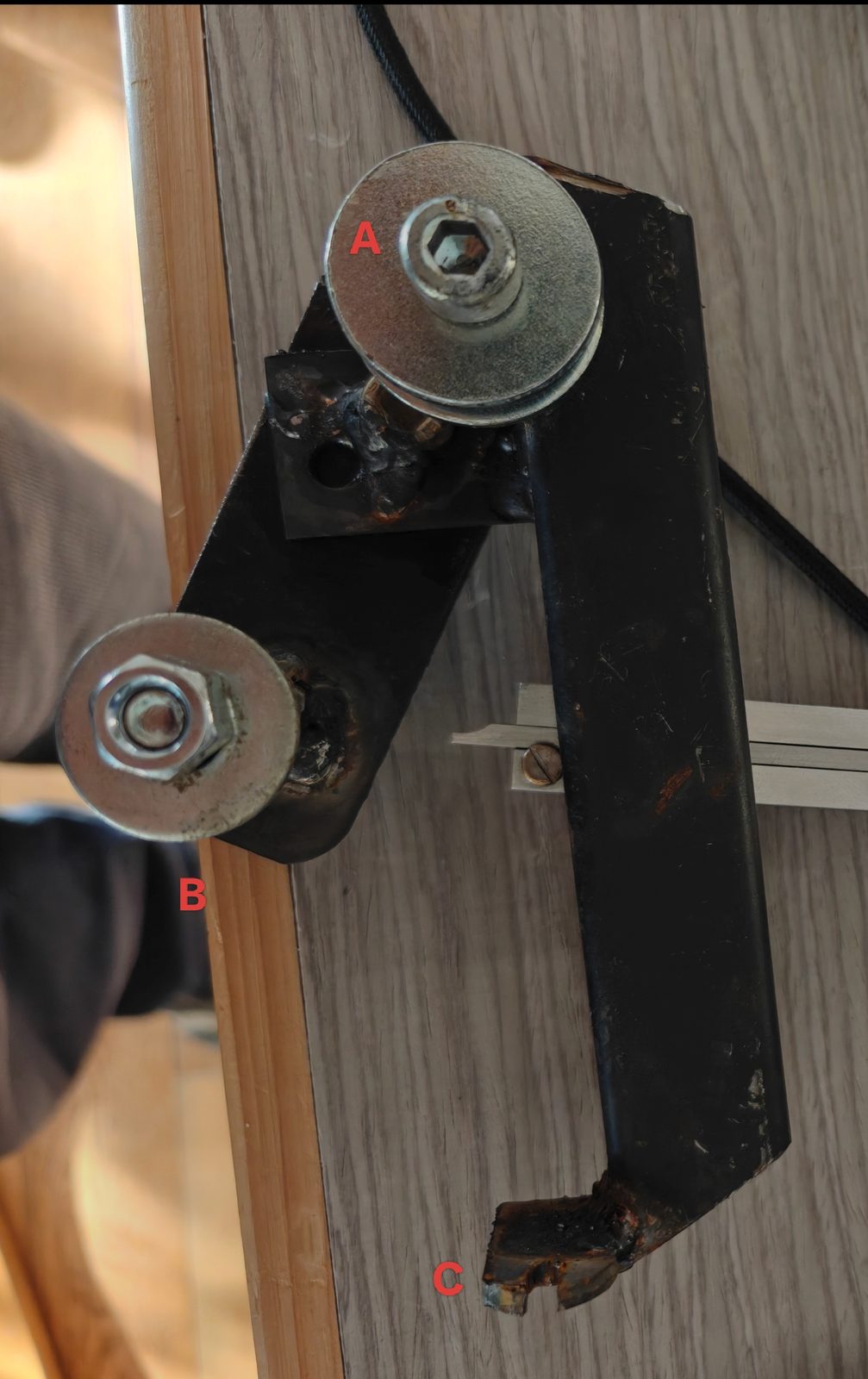
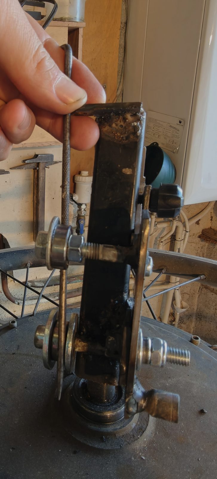
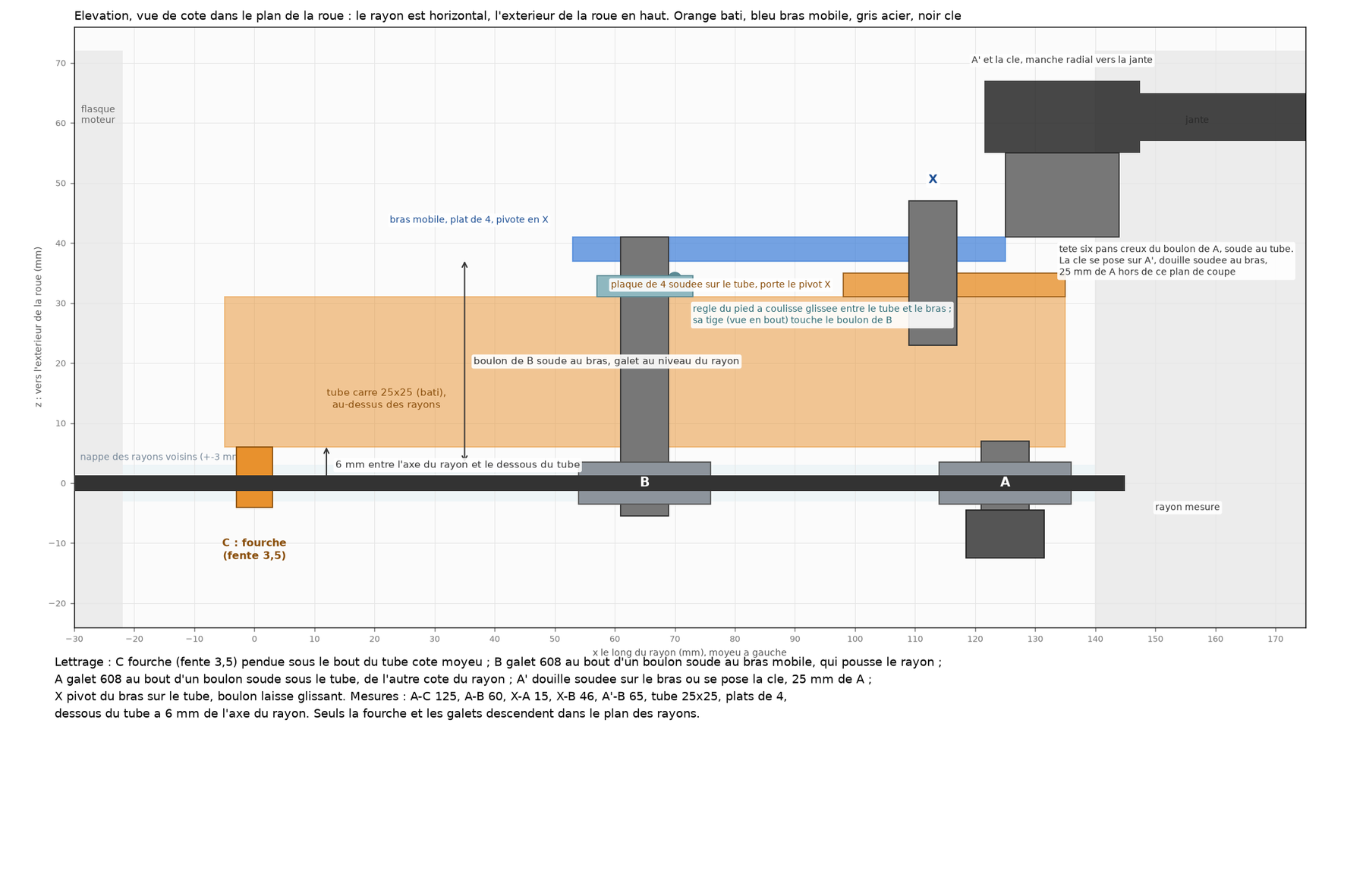
The frame is a 25 mm square tube that sits above the spoke, 6 mm from it, and stays entirely clear of the neighbouring spokes. Only three elements reach down to spoke level: the fork at the hub end, a 3.5 mm slot hanging under the end of the tube, and the two bearings, each at the end of a vertical bolt. The first bearing, A, sits at the end of a bolt welded under the tube, 125 mm from the fork. The second, B, on the other side of the spoke, 60 mm from A, sits at the end of a bolt welded to the moving arm.
The moving arm is a 4 mm flat lying above the tube. It pivots on a bolt left loose, X, set in a 4 mm plate welded on the tube, 15 mm from A and 46 mm from B. A socket welded on the arm, 25 mm from A, takes the square drive of the torque wrench, whose handle points radially towards the rim. When the wrench pushes, the arm rotates about X and B presses on the spoke with the torque divided by 46 mm: 111 N at 5 Nm, 156 N at 7.
The caliper is slipped between the arm and the tube, beside the pivot plate, and its depth rod touches B’s bolt. It reads directly the displacement of B relative to the tube, that is, the deflection of the spoke relative to the chord joining its two fixed supports, A and the fork.

Act V: the first numbers, and a mechanics lesson
First surprise, and the one that taught me the most. On a free spoke, held in the air in the tool, I read 3.4 mm at 3 Nm, 4.6 mm at 5 Nm and 5.9 mm at 7 Nm. Three points perfectly aligned, 0.625 mm per Nm, but a line that does not pass through zero: there is 1.5 mm of reading before the spoke starts to resist. That is the assembly play, the 3.5 mm slot on a 2.6 mm spoke, the loose pivot, the bolts. It is constant, at least those three times, and it subtracts out. But it forbids reading a single measurement without having characterised it.
Second surprise: that slope was two and a half times lower than the calculation predicted for a free 2.6 mm spoke on two supports. I first looked for where the torque was going. It was going nowhere. The beam was wrong: a spoke you hold by the end between two fingers is no longer free, and above all, a spoke mounted in a wheel has its ends held, the elbow in the flange hole 20 mm from the fork, the nipple in the rim 15 mm from roller A. With ends held that close to the supports, the bending stiffness is four times that of a free beam. So the share of tension in what the tool reads falls back to about 40 % around 1,000 N. Less than hoped, but still very measurable.
On the mounted spoke, I read 3.8 mm at 7 Nm. Once the play is subtracted, 2.3 mm of elastic deflection remain, and the model converts them into about 850 N, between 640 and 1,140 depending on whether the play is really 1.2 or 1.8 mm. For a 2.6 mm spoke on a hub motor, the commonly targeted order of magnitude is 1,000 N. So that spoke is not far off, but the figure is still a calculation, not a measurement: the exact position of the supports and how firmly the elbow is held weigh 20 % on the result. To compare spokes with each other, the model is enough. For newtons, it will take a bench.
And the stress in the spoke, because the tool can bend what it measures. The free spoke took 6.7 mm of true deflection over 125 mm at 7 Nm without keeping any set, which corresponds to 1,300 MPa at the surface: the yield point of a drawn spoke, no higher. On a mounted, slack spoke, 7 Nm climbs to 1,500 MPa. The right setting is 5 Nm: between 800 and 1,100 MPa whatever the tension, 0.07 mm of reading per 100 N around 1,000 N, and the wrench in the part of its range where its 4 % is guaranteed. Those 4 % of torque read as 8 % of tension; it is the dominant uncertainty, and no lever reduces it. For equalising a wheel, it is enough.
Expected caliper reading at 5 Nm, including the 1.5 mm of play, for a mounted spoke:
| Spoke tension | Reading at 5 Nm |
|---|---|
| 0 N | 4.57 mm |
| 400 N | 3.68 mm |
| 800 N | 3.19 mm |
| 1,000 N | 3.03 mm |
| 1,200 N | 2.89 mm |
| 1,600 N | 2.68 mm |
The curve flattens towards high tensions: beyond 1,200 N the tool discriminates poorly. For my wheel, that is not the problem.
Act VI: what remains to be done
Everything above rests on a handful of readings. The next step is to make the tool talk properly, in this order.
- Ten readings at 5 Nm on the same spoke, without touching the nipple, the slider reset to zero between each, the wrench handle always in the same direction. That is the real scatter of the tool, the one that matters.
- Five readings at 3 Nm on the same spoke, to check that the 1.5 mm of play does not move.
- A zero-tension control point, on the free spoke, holding only the tube this time.
- A calibration bench: an extrusion, a spare spoke, a load scale, from 600 to 1,200 N. That is what will turn millimetres into newtons without going through the model.
- Then the map of all thirty-six spokes, the search for the target tension, and the replacement of the broken spoke, noting exactly where it broke.
If you break spokes on a hub motor, remember this above all: the sound will not give you the level, neither will a classic bicycle tension meter on 12G, and a mounted spoke behaves differently from a free one. The rest is scrap steel, a click wrench and a caliper.