Neato error 4202 “battery discharged”: the day my vacuum decided it was dead
A D800 cut off from its cloud, a battery declared “needs replacing”, and three wires on a two-euro ESP32 to ask it what it really has to say
Two minutes, if your Neato is blinking red with error 4202
- The symptom: red light, error 4202, “battery discharged”, the robot refuses to charge or to start. On the D8, D9, D10 and D800, the app (as long as it existed) added that the battery’s charge counter had been exceeded.
- What it means: not necessarily that the battery is dead. It contains a chip that talks to the robot; it’s what the chip says that triggers the error. Swapping the cells (the “batteries” inside) doesn’t change what it says.
- What we found by getting it to talk with a two-euro microcontroller: no fault, no protection tripped, a counter at 1,547 cycles, and a “don’t charge me” that was nothing but its sleep mode.
- What we did: backed up its memory, reset the counter to zero. The robot worked again… for a day. Update, September 1: the real cause was elsewhere — a weaker salvaged cell tripping the over-voltage protection on every charge (240 times in three days). Charging voltage lowered, gauge put back into learning mode, under observation (see Where things stand).
- Epilogue: the “dead” original cells, run through a capacity tester, still deliver 1,819 to 1,916 mAh out of a nominal 2,500. They had nothing to answer for either.
- Before buying a battery: read How to reproduce it. You need a soldering iron, three wires, an ESP32 and an evening. No €150 manufacturer programmer, no password to crack.
This post is meant to be readable with no background in electronics: every technical term is explained the first time it appears, and a glossary recaps them at the end. The “Going deeper” boxes unfold for those who want the registers, the addresses and the bytes.
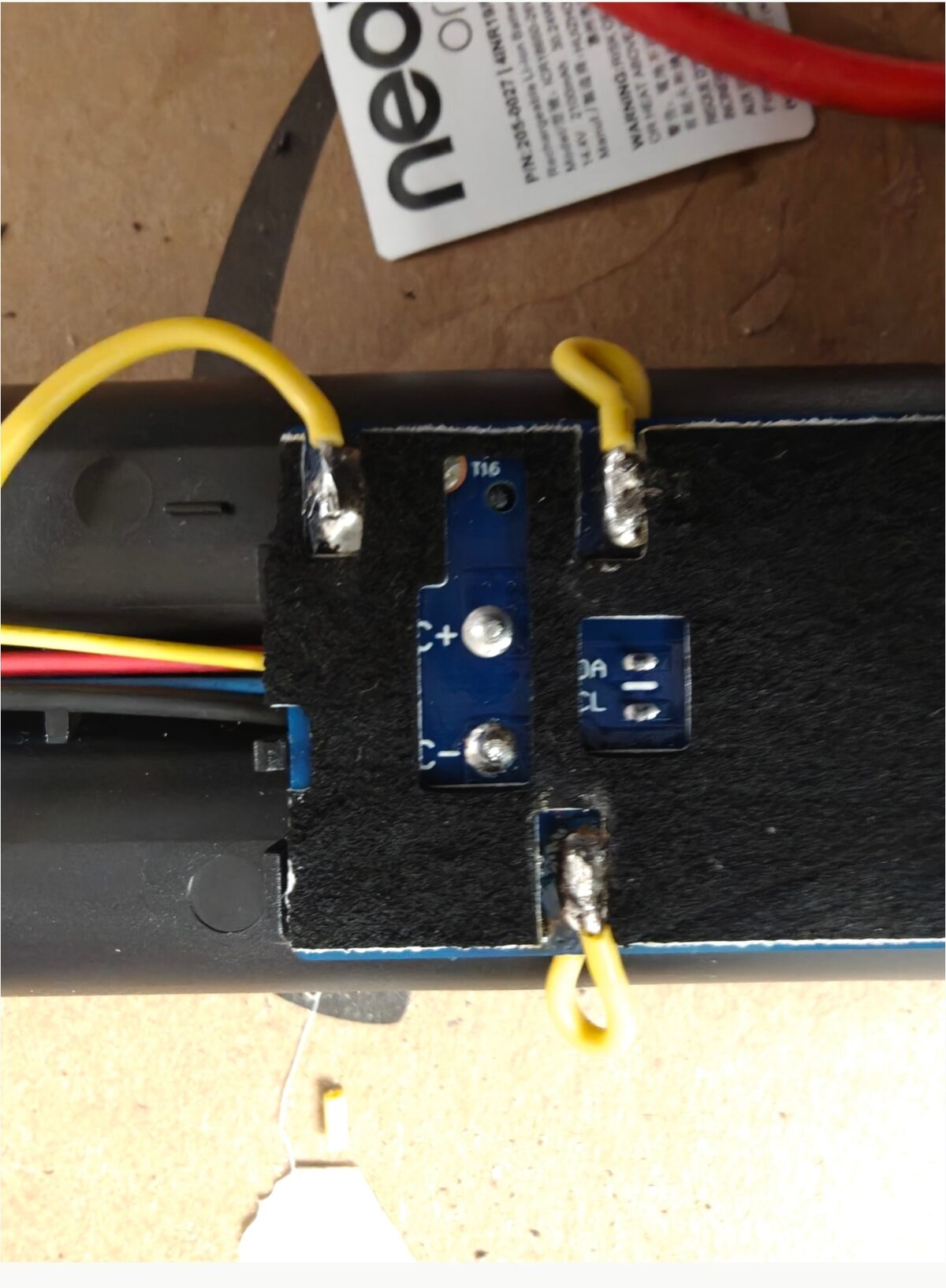
The pack’s board, once the sleeve is opened. The two small pads marked “DA” and “CL”, on the right, are all we need. The big ones in the center, C+ and C−, are the ones we don’t touch.
A cloud switched off, then a button that dies
My robot vacuum is a Neato D800. A good robot: a spinning LIDAR (a small laser radar that rotates on top and measures the distance to the walls), a map of the house, no-go lines you draw in the app, €600 at the time. In 2023, Neato Robotics shut down. Vorwerk, the parent company, kept the servers running for a while — the “cloud”, meaning the remote computers without which the app, the maps and the scheduling don’t work — then announced on October 6, 2025 (local copy) that this cloud was going dark. “Your Neato robot will continue to function manually. Simply press the button once to launch a full house run.” A €600 robot demoted to a one-button vacuum, by press release.
And then, a few months later, the button itself stopped responding. Red light, error 4202, “battery discharged”. The app, in its dying breaths, specified that the battery’s charge counter had been exceeded and that it needed replacing. Original battery: €90, when you can find one. Compatible: €30 to €50, with the well-documented risk on the forums that the robot rejects it.
This post tells how we went from “dead robot, dead battery” to a battery that explains by itself what’s wrong — without buying anything, with three wires and a microcontroller that costs the price of a coffee. It also tells of a false hope, because that’s what happens when you investigate for real. It pauses on what this investigation would have cost me three years ago, before an AI could read a 250-page manual on my behalf, and on the remarkable little chip that manages this battery. And it explains why this story leaves me with a bitter taste about the way we build objects.
First reflex: the cells
A robot battery is a housing containing several cells — lithium accumulators in the 18650 format (18 mm in diameter, 65 mm long, the look of an oversized AA) — wired in series and managed by a small circuit board. A “discharged” battery that won’t recharge is classically a case of dead cells. So I did what every tinkerer does: opened the pack, desoldered the four cells, soldered in four salvaged cells in their place — mismatched, which will matter later —, closed it back up.
Result: still error 4202.
Multimeter in hand (the instrument that measures voltage, i.e. electrical “pressure”, in volts), though, everything was perfect. 4.1 V on every cell, which is a full lithium cell; 16.4 V across the pack; 16.4 V at the output connector, meaning the protection circuit — the electronic switch that can isolate the cells in case of danger — was letting current through. The thermistor (a resistor whose value changes with temperature, which the robot reads to monitor the battery) showed 6 kΩ, a normal value for a warm room. The robot was holding a battery charged to 95% and in good health, and it was displaying “battery discharged”.
That’s the moment you understand the problem isn’t the battery. It’s what the battery says about itself.
Going deeper: measuring without getting burned
The pack is 14.4 V nominal (four cells in series, “4S”), 16.8 V when charged. That’s not a dangerous voltage for skin, but a short circuit — connecting plus and minus directly — on 18650s lets through tens of amps: enough to weld a pair of pliers, melt a sleeve or set a cell on fire. Simple rules: no bracelet, no ring, a single metal tool at a time, and measure on the B+ / B− pads (cell side) or C+ / C− (connector side) without ever bridging them. The thermistor (a 10 kΩ NTC at 25 °C: its resistance drops when it gets hot) is read between the temperature wire and the minus.
If the voltage is good on the cell side but zero at the connector, the protection circuit has cut out: there, it really is the chip that decided, and we’re squarely in the subject of this post.
The battery has a brain
The packs in the latest-generation Neatos (D8, D9, D10, D800) are “smart batteries”: next to the cells, the small board carries a fuel gauge, a chip — an integrated circuit, a tiny sliver of silicon holding a specialized computer — from Texas Instruments, the bq40z50-R2. It’s the gauge that measures the current, adds up what goes in and what goes out, derives the state of charge from that, cuts out in case of overvoltage or overheating — and it’s the gauge that talks to the robot, over a serial bus: two wires carrying digital messages, one wire for the data and one for the clock that paces the conversation. The protocol (the language spoken on those wires) is called SMBus, an industrial cousin of the I²C that every Arduino tinkerer knows. An extra blue wire in the pack’s connector carries this conversation up to the robot.
The robot doesn’t measure the battery’s voltage. It asks the gauge: “how charged are you?”, “what charging current do you want?”, “what voltage?”, “how many cycles have you done?”. And it obeys whatever the gauge answers. If the gauge says “0%” or “don’t charge me”, the robot displays “battery discharged”, whatever the electrical reality three centimeters away.
This architecture isn’t absurd: a gauge inside the pack knows the cells’ history, handles their balancing (keeping all four cells at the same level of charge, failing which the weakest wears out first), and protects effectively against thermal runaway (the chain reaction that sets a mistreated lithium cell on fire). But it has a consequence: replacing the cells does not reset the gauge. The cycle counter, the learned capacity, the error flags (yes/no boxes the chip ticks when it detects a problem) — all of that lives in the chip’s memory, not in the cells. You replace the heart, the brain keeps its memories.
On the forums, the trail usually ends there. The chips in the D3–D7 packs are from an obscure manufacturer and locked; for the bq40z50 “you need an EV2400 and bqStudio” — Texas Instruments’ official adapter, €150, and its Windows software — and nobody really knows which data the robot checks. End of story, buy a battery.
Going deeper: SMBus, SBS and what “smart battery” means
The Smart Battery System (SBS) is a 1990s standard, born for laptops. An SBS battery is a device at SMBus address 0x0B — on a shared bus, each chip has a number so you know who you’re talking to; the 0x… notation means the number is written in hexadecimal, base 16, the programmers’ habit — that answers about a hundred standardized commands, each designated by a number: 0x09 voltage, 0x0A current, 0x0D relative state of charge (RSOC, the “battery percentage”), 0x10 full charge capacity, 0x17 cycle count, 0x14 / 0x15 requested charging current and voltage… What a command returns is called a register: a small memory slot readable from the outside. A “smart” charger reads those last two registers and supplies exactly what it’s asked for. At zero, it supplies nothing.
On top of that, the bq40z50 adds a catch-all command, ManufacturerBlockAccess (0x44), through which you read the internal status registers (safety status, permanent failures, transistor states) and, with sufficient access, the entire configuration flash memory — the memory that survives power-off, like a USB stick —, 8 KB from addresses 0x4000 to 0x5FFF, where the cycle counter, the design capacity, the protection thresholds and some fifty options live.
Three access levels exist: Sealed (standard registers readable only), Unsealed (unlocked by a 32-bit key) and Full Access (everything, including writing to flash, behind a second key). TI recommends sealing before leaving the factory.
Three wires and a two-euro ESP32
Except that the bq40z50 is a publicly documented chip. Texas Instruments publishes its Technical Reference Manual — the reference manual, 250 pages describing every register, every command, every memory address (local copy of the PDF, 1.6 MB). And SMBus, any microcontroller — a complete computer on a chip, a few euros, the kind found on an Arduino board — can speak as soon as it has two I²C pins.
I have a drawer full of ESP32-C3 “Super Mini” boards: a board the size of a postage stamp, two euros apiece, that plugs into USB and programs like an Arduino.
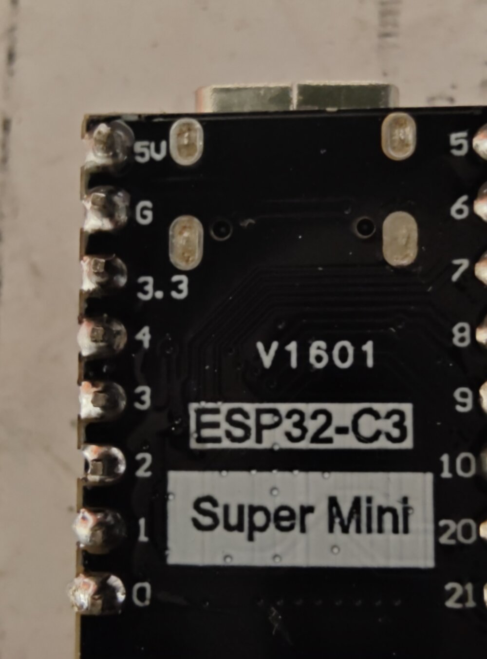
On the pack’s board, two test pads — contact points deliberately left by the manufacturer to hook up its end-of-line test equipment — are silkscreened DA and CL: data and clock, the two SMBus wires. One wire on DA, one on CL, one on the cells’ minus, and on the other end the GPIO 4, GPIO 5 (GPIO: a microcontroller’s numbered input/output pins) and GND (ground, the shared “zero volt”) pins of the ESP32. No component to add, no power supply to provide: the gauge is powered by its cells and the ESP32 by its USB.
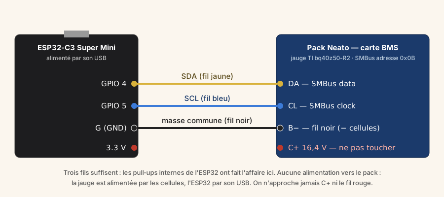
On the software side, two hundred lines of Arduino, written with an AI (Claude) that read the manual on my behalf: we read the standard registers (voltage, current, state of charge, cycle count, per-cell voltages), then the internal status registers — safety status, permanent failures, state of the charge and discharge transistors —, then we copy out the flash memory. Nothing is written without an explicit order. We listen.
Going deeper: the wiring, the pull-ups and the code
| Pack (BMS board) | ESP32-C3 Super Mini |
|---|---|
| DA pad (SMBus data) | GPIO 4 (SDA) |
| CL pad (SMBus clock) | GPIO 5 (SCL) |
| Black wire (cells’ −, B− pad) | G (GND) |
SMBus needs pull-up resistors (they gently pull each line toward 3.3 V when nobody is talking, failing which the signal floats) on both lines. The ESP32’s internal resistors (≈ 45 kΩ) were enough here at 100 kHz over ten centimeters of wire; if the chip doesn’t answer the I²C scan, add two 4.7 kΩ resistors between each line and the ESP32’s 3.3 V. The gauge tolerates 3.3 V on its bus lines; we never connect the ESP32’s 3.3 V or 5 V to the pack.
The sketch — that’s what Arduino calls a program — (bq40z50-reader.cpp, platformio.ini) runs in a loop: every ten seconds, a full readout on the serial port (the text channel between the board and the computer, read in a “serial monitor”) at 115200 baud (the link speed). It writes to the gauge only on three letters typed into the monitor: r (chip reset), c (cycle counter to zero), C (counter restored to its original value). Everything else is reading.
What the chip said
First readout, on the serial monitor:
Voltage            : 16386 mV
RSOC               : 97 %
RemainingCapacity  : 2343 mAh
FullChargeCapacity : 2437 mAh
DesignCapacity     : 2500 mAh
CycleCount         : 1547
ChargingCurrent    : 0 mA
ChargingVoltage    : 0 mV
Cellules           : 4094 / 4097 / 4100 / 4095 mV
ManufacturerName   : BLUEWAY-
DeviceName         : bq40z50-
ManufactureDate    : 2022-01-09
OperationStatus    : PRES DSG CHG SEC0  -> sécurité : FULL ACCESS
SafetyStatus       : (aucun flag)
PFStatus           : (aucun flag)
To read this: mV and mA are millivolts and milliamps (thousandths of a volt and of an amp); mAh, milliamp-hours, measure a quantity of stored energy — 2,437 mAh is enough to supply 2.4 A for one hour; RSOC is the displayed battery percentage; FullChargeCapacity is what the gauge thinks it can store today, DesignCapacity what the pack stored when new.
Three things jump out.
The gauge is in great shape. No safety fault, no permanent failure, charge and discharge transistors conducting (the transistors, or FETs, are the electronic switches through which the gauge allows or cuts charging and discharging), state of charge estimated at 97% — consistent with 4.1 V per cell. It isn’t “discharged”, and it knows it.
It isn’t even locked. The security level is FULL ACCESS: the chip’s most permissive mode, the one TI recommends leaving before shipping from the factory. No password to crack, no key to guess. The entire memory is readable and writable. The pack manufacturer delivered the house with the keys in the door.
And yet it tells the robot not to charge it. ChargingCurrent = 0 mA, ChargingVoltage = 0 mV. Those are the two registers a smart charger reads to know what to do. At zero, they mean: “don’t send any current”.
And the counter: 1,547 cycles. A cycle, for a gauge, is a cumulative discharge equivalent to one full battery — two half-discharges make one cycle. For a battery manufactured in January 2022, that’s one cycle per day for four years — plausible for a robot that runs daily. It’s also the number the app had held against me.
Going deeper: reading the status flags
OperationStatus (command 0x44 + 0x0054) is a 32-bit word — thirty-two slots worth 0 or 1, each one a flag. The ones that matter here: PRES (the robot is detected), DSG and CHG (discharge and charge transistors conducting), SEC1:SEC0 (security level: 01 = Full Access, 10 = Unsealed, 11 = Sealed), PF (permanent failure: the pack has condemned itself), XCHG / XDSG (charging / discharging forbidden), SLEEP (remember that one). SafetyStatus (0x0051) lists the active protections — overvoltage, undervoltage, overcurrent, temperature; PFStatus (0x0053) the permanent failures, the ones no reset clears: open cell, blown fuse, unrecoverable imbalance. Everything was at zero.
Seventeen thousand lines of manual, and a false hope
The question becomes: why is the gauge refusing to charge? The TI manual precisely lists the cases in which ChargingVoltage() drops to zero: charge transistor cut by a protection, temperature out of range, permanent failure, pack declared “removed”, charger overvoltage detected. We checked them all, register by register. None was active. Temperature 26 °C, temperature region “recommended”, voltage region “high”, all green.
We also explored a seductive lead: the bq40z50 has a cycle-count degradation feature, which deliberately reduces the charging voltage and current as the pack ages — planned obsolescence in the literal sense, enabled by a configuration bit. We read that bit in the flash memory. It was zero. Neato hadn’t enabled it. The charging table said 4.2 V per cell and 1.5 A across all temperature ranges. On paper, the gauge should have been announcing 16.8 V and 1,500 mA. It was announcing 0 and 0.
Before going further, we did what you must always do before touching a memory you won’t be able to buy back: a full backup. 8 KB, 256 blocks of 32 bytes (a byte is eight bits, the smallest unit of memory), read one by one and stored in a file (here it is, if yours is the same pack). If a write goes wrong, everything can be put back.
Then we tried the dumbest thing in the world. The manual documents a command 0x0041 : Reset — a chip reset: its RAM (the working memory, wiped at every restart) is rebuilt from flash, nothing is written. The equivalent of “have you tried turning it off and on again?”. One letter r sent over the serial monitor, three seconds of waiting:
>>> Envoi MAC 0x0041 Reset
ChargingCurrent    : 1500 mA
ChargingVoltage    : 16800 mV
RSOC               : 97 %
FET DSG ON, FET CHG ON, PF inactif
Victory, we thought. Pack reassembled, robot placed on its base: no more error, it charges, it announces it’s ready. I wrote a first version of this post that very evening, with a triumphant conclusion about the cycle counter the robot “had never cared about”.
The next morning, red light, error 4202.
The symptom that vanishes when you look at it
Pack hooked back up to the ESP32. ChargingCurrent : 0 mA, again. Reset: 1,500 mA. And this time, instead of crying victory, we let it run and watched the clock.
At 3 seconds: 1,500 mA. At 20 seconds: 1,500 mA. At 31 seconds: 0 mA — and in the same readout, a flag that wasn’t there ten seconds earlier: SLEEP. Two attempts, two full readouts compared line by line: between 20 and 31 seconds, the only thing that changes is that flag.
The gauge falls asleep. As soon as almost no current is flowing (less than 10 mA, a threshold set in its configuration), it goes into standby to spare its cells, and in that state it announces “charging current: 0”. The reset never fixed anything: it woke it up for thirty seconds. On the bench, with an ESP32 that draws nothing, it went right back to sleep. Inside the robot, which pulls a few hundred milliamps, it stays awake and announces 1,500 mA. The “don’t charge me” was never the problem. It was a laboratory mirage.
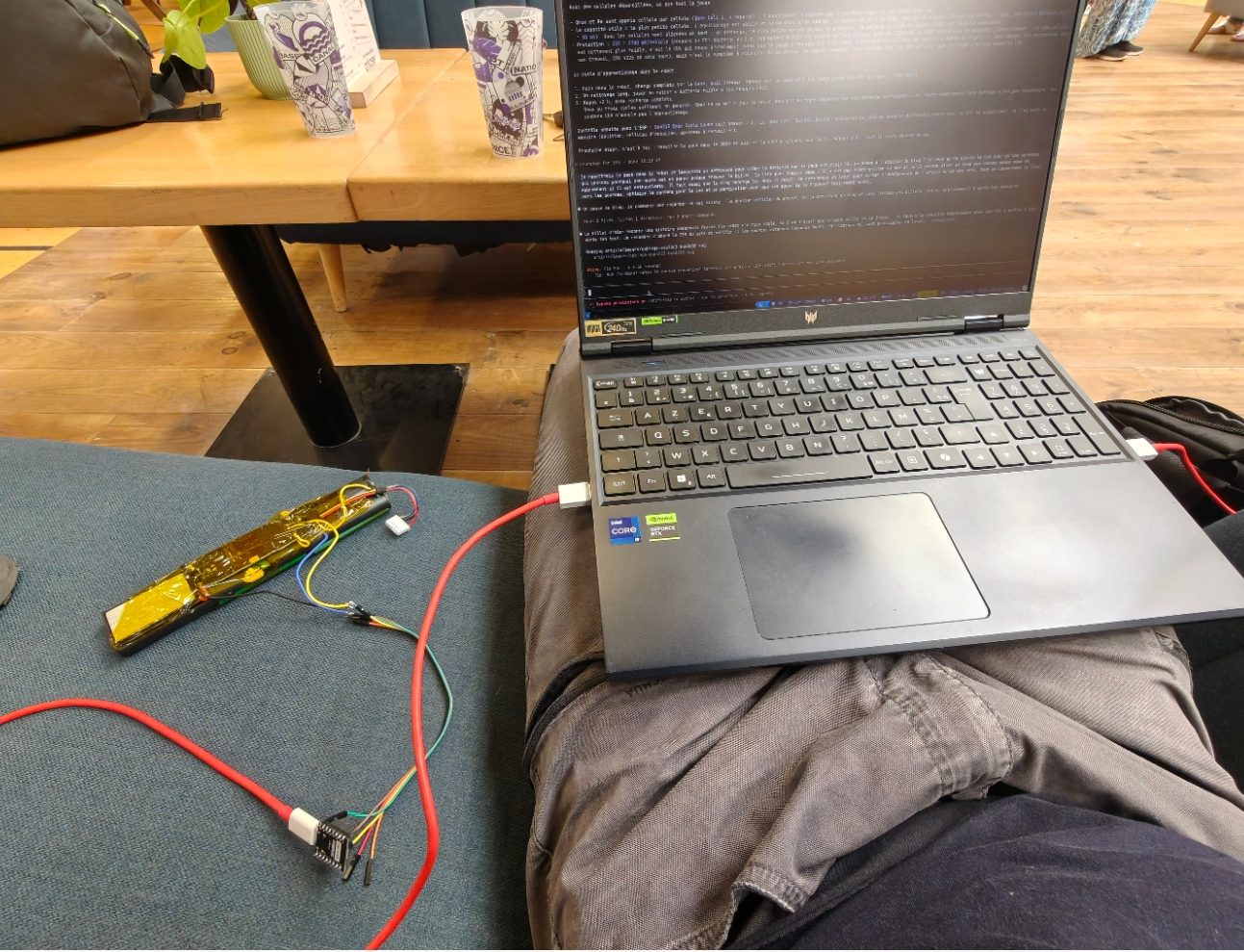
The next morning’s laboratory: a couch, the pack under kapton (the yellow adhesive tape that insulates and withstands heat), the ESP32 at the end of three wires, and a terminal comparing readouts ten seconds apart.
It’s a lesson I already knew and still had to relearn: when a symptom disappears at the moment you observe it, it’s probably the observation that made it disappear. You have to watch what comes back, not what goes away.
Going deeper: the sleep configuration, and an imprecise doc
In flash, DA Configuration (0x4A7D) is 0x001F: four cells, NR = 1 (pack declared non-removable), IN_SYSTEM_SLEEP = 1 and SLEEP = 1. Sleep Current (0x48A3) = 10 mA, Bus Timeout = 5 s. The TRM (§ 4.12, table of conditions for ChargingVoltage() = 0) only provides for zeroing in sleep if FET Options[SLEEPCHG] = 0; here FET Options (0x4887) is 0x7D, so SLEEPCHG = 1, and the charge transistor does in fact stay conducting in sleep. The zeroing of ChargingCurrent() / ChargingVoltage() happens anyway. Real behavior has the last word over the doc — one more reason to measure.
This configuration is the factory one, it hasn’t moved: the robot has always lived with a gauge that dozes off at the slightest pause. The Neato simply wakes it up by drawing current.
The counter
That left the original suspect, the one the app had named: 1,547 cycles. The gauge itself couldn’t care less — cycle degradation is disabled, we checked. But the robot reads that number (CycleCount, command 0x17), and an embedded piece of software (a firmware: the program burned into the robot) that displays “charge counter exceeded” necessarily has a threshold somewhere.
The counter is a plain two-byte value in flash, at address 0x4340. In Full Access, you write it the way you read it: a block command, the address, two bytes. We wrote zero.
>>> CycleCount SBS avant = 1547 ; écriture DF 0x4340 = 0
>>> relecture 0x4340 : 00 00  (OK)
>>> CycleCount SBS après écriture = 0
Immediate, no reset, no safety flag raised. A brand-new battery, in the eyes of anyone who only looks at that number.
Going deeper: writing to the data flash
TRM § 14.1.67: a flash write is an SMBus block write (sending a packet of bytes in one go) on command 0x44, whose block is the start address (little-endian: least significant byte first) followed by 1 to 32 bytes of data. For CycleCount = 0: 0x44, length 4, 0x40 0x43 0x00 0x00. The block is then read back (block write of the address alone, then block read of 0x44, which returns the address and 32 bytes) to verify. The SBS value 0x17 followed without a reset. The sketch’s C command puts back 0x0B 0x06 (1547) if you want to revert.
What we did not touch, and why: Qmax (the cells’ chemical capacity as the gauge learned it, 0x4306…0x430E, five times 2650 mAh) and the internal resistance table date from the original cells; Design Capacity (0x48E5) is 2500 mAh; the state of health the gauge announces (FullChargeCapacity / DesignCapacity) therefore swings between 73% and 92% depending on the time of day. One could cheat by lowering Design Capacity, or force Qmax. We preferred to let the gauge relearn honestly over full cycles — see below. The full, decoded map of the flash is here.
The twist
September 1, evening: red light. Error 4202. The robot had lasted one day.
Third time the same script plays out: touch the pack, plug it back in, the robot runs again, and the next day it stops. Resetting the gauge had “worked” for an evening; zeroing the counter, for a day and a few cycles. Looked at closely, those two “victories” share one thing that isn’t the fix: each time, the pack was unplugged and plugged back in. The robot reboots, forgets its “battery discharged” state, tries again — and runs into the same cause, which we hadn’t found.
This time, before any reset, the pack went onto the ESP32 as it was. Cycle count: still 0. No active protection, no permanent failure, gauge in perfect health — the same reassuring readout as the first evening. Except we had learned to distrust reassuring readouts, and we went to read a region of the flash we had never decoded: the lifetime data (Lifetimes), the logbook the gauge keeps about itself since it left the factory — extreme voltages seen by each cell, how many times each protection has tripped, and at which cycle the last one happened.
Compared with the August 29 backup, it said this:
                              Aug 29       Sep 1
COV (cell over-voltage)       6            246   (+240 in three days)
Lifetime max V, cell 4        4213 mV      4293 mV   (COV threshold: 4225)
Valid charge terminations     21813        21813 (none since the re-celling)
Cells at rest                 —            3986 / 3986 / 3995 / 3939 mV
Two hundred and forty trips of the over-voltage protection in three days, all on cell 4 — and not a single charge run to completion. The original pack had seen six in four years.
The explanation fits in one picture. Four cells in series are four buckets filled through the same hose: if one is smaller, it overflows first. Cell 4 of my salvaged set has less capacity than the other three — at rest it sits lowest (3.94 V against 3.99), and on charge it is the first to cross 4.225 V. The gauge then does its job: it opens the charge transistor, waits for the cell to drop back to 4.1 V, closes it again, opens it a second later. Two hundred and forty times. The robot’s charger, meanwhile, sees a charge that never terminates; after a while its firmware draws the only conclusion it knows: “battery discharged”, 4202.
The cycle counter had nothing to do with it — or not everything. For the original pack we will never know: I changed two things at once. Its lifetime data, though, shows 67 under-voltage events, the last one at cycle 1547; the 41 mΩ cell sagging in the middle of a vacuuming run is at least as good an explanation as the counter. Error 4202 is a catch-all.
The new attempt. The clean solution is to run the four salvaged cells through the tester, as with the originals, and rebuild a pack from the four best-matched cells among the eight. In the meantime, the gauge allows a stopgap with no soldering iron, still through the three wires — and that is what we did the same evening:
- charging voltage lowered from 4200 to 4100 mV per cell: the pack stops at 16.4 V instead of 16.8; cell 4 stays below the over-voltage threshold, at a cost of about 10% runtime;
- reference capacity brought down to 2100 mAh (it had stayed at 2500, the new pack’s figure), the cells’ chemical capacity aligned with it;
- gauge put back into learning mode: its learned values (chemical capacity, resistance table) dated from the 2022 cells; one bit tells it to relearn everything over the next cycles.
Reset: the gauge reports 16,400 mV and 1500 mA, an estimated full-charge capacity of 1792 mAh, no fault. Pack closed up, robot on its dock. This time, no victory lap: we wait a few days, then reopen the gauge’s logbook. If the over-voltage counter still reads 246, that was it.
Going deeper: the lifetime data, and what we wrote
The Lifetimes region spans flash 0x4380 to 0x43F7 (TRM ch. 18): min/max voltage of each cell (0x4380), then for each protection an event counter and the cycle count at the last event — COV at 0x43A0/0x43A2, CUV at 0x43A4/0x43A6, and so on —, then valid charge terminations (0x43D0), Qmax/Ra updates (0x43D4…), running time. The COV threshold lives at 0x494E (4225 mV here, 1 s delay, 4100 mV recovery at 0x4959).
Writes of September 1, all read back afterwards: charging voltage per cell in the charge algorithm’s five temperature regions (0x4A19, 0x4A21, 0x4A29, 0x4A31, 0x4A39: 4200 → 4100); Design Capacity 0x48E5 = 2100 mAh and 0x48E7 = 3024 cWh; Qmax cells 1–4 and pack 0x4306–0x430E = 2100; Qmax Cycle Count 0x4310 = 0; Update Status 0x4312 = 0x04 (Impedance Track enabled, “not yet learned”: the gauge will redo Qmax, then the Ra table, over the next cycles, TRM 15.13.8.2 and 6.4.6); then reset 0x0041. Checked before writing: the “fully charged” flags (FC/TC) are set here by valid charge termination (current under 130 mA, cell within 75 mV of the charging voltage), not by a fixed 4200 mV threshold — lowering the voltage doesn’t break them. Margin on cell 4: some thirty millivolts under the threshold; the sketch has a command to go down to 4050 if that isn’t enough. Commands: v/w/V (voltage 4100 / 4050 / 4200), d/D (capacity and learning / factory values).
Where things stand
Status as of September 1, 2026: under observation. Error 4202 came back on September 1 after a day of operation; the real cause is a weaker salvaged cell tripping the over-voltage protection on every charge, 240 times in three days (see The twist). Stopgap applied the same evening through the three wires: charging voltage 4100 mV per cell, reference capacity 2100 mAh, gauge relearning. The robot is on its dock; verdict in a few days, by reopening the gauge’s logbook — if the over-voltage counter hasn’t moved, that was it. Still not a single part bought.
And then there’s the epilogue I hadn’t seen coming. The four original cells, the ones I had desoldered at the start because “the battery was dead”, were lying around on the bench. For good measure, I measured them: 3.6 V each. None is below the threshold where a lithium cell condemns itself. So I ran them through a capacity tester — a Liitokala Lii-500, a thirty-euro charger-analyser, in “NOR TEST” mode: it charges the cell fully, then discharges it at constant current while counting the milliamp-hours that come out, then recharges it. That’s the only honest way to know what a cell is worth: empty it with a stopwatch running.
The verdict, on cells rated 2,500 mAh when new:
| Cell | Measured capacity | Share of nominal |
|---|---|---|
| A | 1,916 mAh | 77% |
| B | 1,912 mAh | 76% |
| C | 1,855 mAh | 74% |
| D | 1,819 mAh | 73% |
The tester also gives each cell’s internal resistance — the electrical “friction” of the chemistry, in milliohms (mΩ): the higher it is, the more the voltage collapses when the robot draws current, and the more the cell heats up instead of delivering. Three cells sit between 16 and 19 mΩ, which is good for 18650s of that age. The fourth is at 41 mΩ: more than double. That’s the pack’s weak link — the one that sags first mid-vacuum, drags the others toward the cutoff threshold and therefore shortens the runtime far more than its 1,819 mAh would suggest.
But none of them is dead. After something like 1,547 cycles, these cells still deliver three quarters of their original capacity: a normal loss, the one you expect from a lithium cell reaching the end of its advertised life. In practice, the runtime would have gone from a full hour and a half to a little over an hour. A slightly less enduring vacuum — not a dead one.
That’s where the story finds its point. The pack that set all this off wasn’t faulty: it was 25% worn, and something — a counter, or more likely its 41 mΩ cell sagging mid-run — decided that was the end. The recelling I did on first reflex probably wasn’t necessary, and done with salvaged cells that were never measured, it added a problem of its own (see The twist); at least it leaves me four working original cells, measured and documented, ready to serve as spares the day the salvaged ones give out.
What it would have cost me three years ago
Let’s be honest about the step I climbed without seeing it.
Three years ago, this story would have ended at the paragraph “First reflex: the cells”. Cells replaced, error still there, multimeter unequivocal: the battery is good. And then? Then, a dead end. I would have searched the forums, found the same threads as everyone else — “you need an EV2400 and bqStudio”, “the chip is locked”, “buy a battery” — and I would have either bought, or put the robot in a closet waiting for a courage that never comes.
Because the rest of the process, which fits here in a few paragraphs, represents work I couldn’t have delivered in a tinkerer’s evenings. Let’s lay it out:
- Identify the chip and find its manual: easy.
- Read the manual: 250 pages, 17,000 lines of dense technical English, written for battery engineers who already know the vocabulary. It’s not about skimming it: you have to find the three tables that say when the charging current drops to zero, the flash write procedure, the map of the 400 configuration addresses, the meaning of every bit in a dozen status registers.
- Learn SMBus at the protocol level (the block read, the block write, command
0x44and its echo, address auto-increment) and write a program that speaks it without error. - Interpret a readout of forty flags and 8 KB of raw bytes, cross-referencing them with the manual.
- Design the experiments: the reset, then — after the false hope — the idea of comparing two full readouts ten seconds apart to isolate the line that changes.
- Write to the flash without breaking anything.
For a competent developer who isn’t a battery engineer, that’s several weeks of evenings, with a real risk of giving up at step 2 — and that’s exactly where the forum threads stop. It’s not that it’s hard in the intellectual sense; it’s that it’s long, and nothing guarantees, at the outset, that those weeks lead anywhere.
With Claude, steps 2 through 6 took two evenings and a morning. The AI absorbed the manual in a few seconds, wrote the sketch in one pass, decoded the registers as they came in, suggested the reset, then — when the reset lied — suggested doing it again while recording everything, and found the SLEEP flag in the comparison. What I kept for myself: the soldering iron, the multimeter, the photos, the decisions (“we don’t touch Qmax, we let it learn”), and above all the doubt: it’s the overnight test in the real robot that disproved the victory, not one more readout.
Two caveats, so as not to turn this into a fairy tale. First, the AI co-signed the false hope: it had the same wrong conclusion as I did the first evening, because we had the same incomplete data. It reads fast, it doesn’t measure on my behalf. Second, it found an error in the manual itself (the sleep mode that zeroes the current while the doc says otherwise) only because we measured the opposite; without the ESP32 hooked up, it would have defended the doc.
But the shift is real, and it seems important to me for repair in general: a body of knowledge that was locked inside a 250-page manual, and therefore reserved to professionals, becomes accessible to someone who can hold a soldering iron and ask a question. Manufacturers count, without saying so, on nobody reading the manual. That assumption just fell.
Focus: the bq40z50, the chip that manages your battery
Since we spent two days with it, let’s introduce it. The bq40z50-R2 is what Texas Instruments calls a battery pack manager: a single chip, the size of a fingernail (32-pin QFN package, the contacts are underneath the package), that does everything a lithium pack of 1 to 4 cells in series needs done. It’s found in a large share of laptop batteries from the past ten years, in power tools, robots, drones, medical batteries.
What it does
- Gauging: it measures the current through a sense resistor (a shunt, a few milliohms) and the voltage of each cell, and derives the state of charge with an in-house algorithm, Impedance Track: instead of merely counting what goes in and out (which drifts over time), it learns the cells’ real chemical capacity (Qmax) and their internal resistance at every cycle, and corrects continuously. That’s what gives recent laptops their precise percentages.
- Protecting: it integrates the AFE (analog front-end: the analog part that monitors voltages and currents in real time, independently of the software) and directly drives the charge and discharge transistors. Per-cell overvoltage and undervoltage, overcurrent in charge and in discharge, short circuit, overheating and undertemperature, each with its thresholds, its delays and its recovery conditions.
- Condemning itself: a second family of protections, the permanent failures (PF), cuts the pack off for good — if need be by blowing an irreversible chemical fuse — in case of an open cell, uncorrectable imbalance, a burnt transistor or too many repeated overvoltages.
- Balancing: during charging, it slightly discharges the cells that are ahead so that all of them reach full together.
- Remembering: cycle counter, extreme temperatures and voltages seen over its lifetime (lifetime data), and a black box that records the last safety events before a permanent failure — enough to perform an autopsy on a dead pack.
- Talking: SMBus, the whole SBS standard, plus the manufacturer’s commands. And authenticating: a cryptographic mechanism (SHA-1 with a secret key) lets the device verify that the pack is genuine. That’s what blocks compatible batteries on some devices.
Its strengths
- Complete and documented. Everything is in a single package, and the manual describes everything: that’s what made this investigation possible. Many competing chips are documented under NDA, or not at all.
- Precise. Impedance Track remains the benchmark in consumer gauging; the estimation error drops to 1% on a well-configured pack.
- Safe by construction. The AFE protects even if the software crashes; permanent failures are non-negotiable.
- Ubiquitous. Tens of millions of units in laptop packs: boards, configuration files and field reports abound.
- Openable. The official bqStudio software and the EV2400 adapter exist, but as we’ve seen, a two-euro microcontroller is enough to read, and often to write.
Its weaknesses
- Complex to configure. Over 400 parameters in flash. Getting Impedance Track to work properly requires a golden image built in a lab: identification of the cell chemistry, calibration, a full learning cycle. A poorly configured DIY pack gauges poorly, and the learning we chose takes several cycles.
- Security depends on the pack manufacturer. TI supplies the locks; it’s the assembler who chooses to close them. The Neato pack was shipped in Full Access. A brand-name laptop battery, on the other hand, is almost always sealed, and without the keys you only read the standard registers.
- Security, conversely, can be a wall. SHA-1 authentication and sealing are precisely what makes some packs unrepairable: a permanent failure on a sealed pack is a trash can, whatever the state of the cells.
- No more than 4 cells in series. For an e-bike (10 to 13 cells in series) you need its big brother, the bq40z80 (up to 7 in series), or another architecture.
- Hard to wire yourself. The QFN package is soldered with a reflow oven or hot air, not an iron; TI’s development boards cost around a hundred euros. In practice, DIY goes through salvaged boards.
What you can do with it, beyond the Neato
- Diagnose a laptop battery before throwing it away. A “dead” Dell, HP or Lenovo pack very often contains a bq40z50 (or a cousin: bq30z55, bq40z80) and six cells, three of which are fine. The ESP32 and this post’s sketch read the state of health, the counter, the faults, and tell you whether it’s the cells or the chip. On a sealed pack you read less, but you read.
- Rearm a pack after recelling. Exactly this post: counter, possibly permanent failure (
PFStatusis cleared by command, in Full Access or with the key), then a learning cycle. - Build a “smart battery” for your own projects. A salvaged BMS board with its bq40z50, four new 18650 cells, and you get a 14.4 V pack that protects itself, balances itself and announces its percentage: for a DIY robot, a field radio, a backup UPS for a home server, a work light.
- Monitor a battery remotely. The ESP32 has Wi-Fi: the same sketch can publish voltage, current, temperature and state of charge over MQTT (a lightweight messaging protocol, the home-automation standard) to Home Assistant or a database. A pack that warns before it gives out.
- Learn. The bq40z50 is a complete course in lithium battery management, with a free manual and a chip you can find in the trash. Everything an electric car’s BMS does, it does in miniature, and it lets you watch it work.
One reservation: all of this assumes an open (unsealed) pack, or one whose keys you have. Laptop manufacturers seal; manufacturers of packs for robots, tools and toys often forget. Check before you dive in — it’s the first readout, and it costs nothing.
What this says
I don’t believe anyone, at Neato or at its battery supplier, decided this robot would die in 2026. I believe something worse: nobody decided it would live.
Look at the layers.
The cloud. The robot was designed to do nothing without a server. When the server goes off, only the button remains. On the D3 through D7, a community managed to hook an ESP32 onto the motherboard’s serial port and give the robots back their autonomy (vacuula/fang, OpenNeato). On the D8 through D10, that port is password-locked. One generation later, the door was locked shut. Not for the user’s safety — for nothing, apparently, except so they wouldn’t touch it.
The authenticated battery. The robot verifies the pack’s identity. The forums are full of D5s bricked after a compatible battery was inserted. The manufacturer calls that security; it’s also, very concretely, a toll booth on the number one wear part.
The counter. 1,547 cycles, and an app that says “needs replacing”. Not because the battery would be unusable — the gauge itself reported it at 97% charged, and the original cells, measured since, still deliver 73 to 77% of their new capacity — but because a number crossed a threshold nobody shows you. The robot was taken out of service over a quarter less runtime.
And the absence of a path. A perfectly documented chip, left in full access, whose counter resets in a single command. No path, anywhere in the product, leads to that command. The diagnosis delivered to the user is “battery discharged”, which is false, and the proposed solution is “buy”, which is expensive.
Obsolescence, here, isn’t a time bomb programmed by a cynical engineer. It’s a sum of non-decisions: nobody budgeted a “reset the battery” feature, nobody wrote the honest error message, nobody left a port open. Each choice is justifiable on its own. Their sum manufactures €600 of waste with a charged battery inside.
The good news is that the same non-decisions leave cracks. The chip wasn’t locked. The pack manufacturer left its test pads in place. TI publishes its manual. And a two-euro microcontroller, plus an AI willing to read 17,000 lines of documentation without complaining, are enough to slip through.
From February 18, 2027, Article 11 of the European battery regulation (local excerpt) will require that portable batteries in appliances be “readily removable and replaceable by the end-user”. That’s progress. But this story shows that “replaceable” isn’t enough: my battery was replaceable, and replacement was precisely what I was being sold as the only way out. What we should demand is that objects tell the truth about their condition, and that they leave a path to correct it. A “reset the battery” button in an app costs an afternoon of development. Silence costs one battery per customer.
How to reproduce it
Hardware: an ESP32-C3 Super Mini (or any ESP32/Arduino with I²C), three wires, a soldering iron, possibly two 4.7 kΩ resistors. The pack must be opened at its circuit board — the sleeve is glued, a box cutter splits it without forcing.
Safety: the cells stay connected throughout the operation. No metal tool near the C+ and C− pads, which carry 16 V and several tens of amps of possible short-circuit current. No bracelet, no ring. The DA and CL pads, on the other hand, sit at 3.3 V and risk nothing.
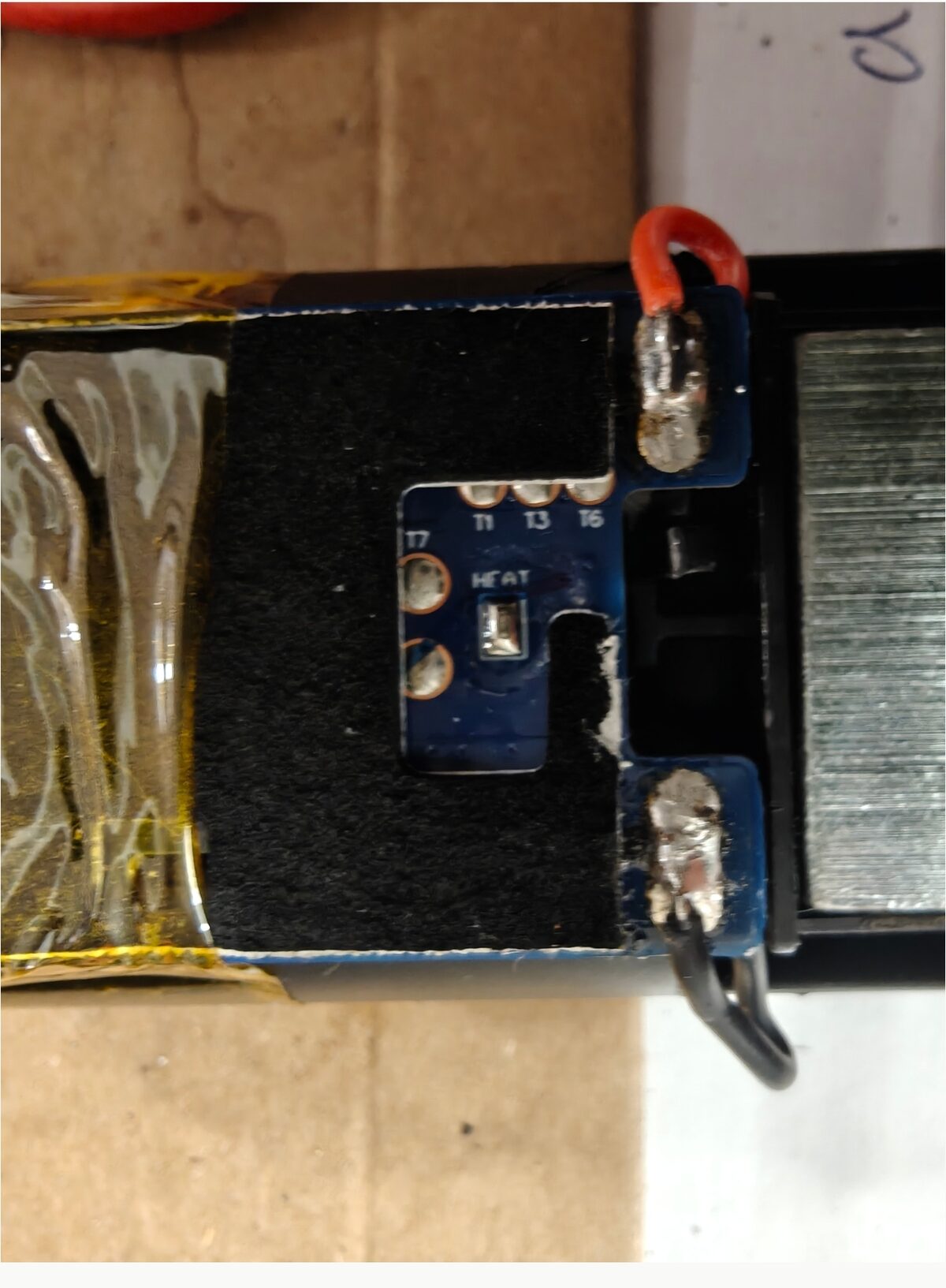
The other side of the board: we don’t touch it, but it shows the manufacturer provided far more test points than the two we care about.
Wiring:
| Pack (BMS board) | ESP32-C3 |
|---|---|
| DA pad | GPIO 4 (SDA) |
| CL pad | GPIO 5 (SCL) |
| Black wire (cells’ −) | G (GND) |
Software: bq40z50-reader.cpp and platformio.ini (PlatformIO is the tool that compiles and uploads the program; Arduino framework, target esp32-c3-devkitm-1). Serial monitor at 115200 baud. The essential registers, at SMBus address 0x0B:
| Register | Contents |
|---|---|
0x09 / 0x0A |
pack voltage / current |
0x0D |
state of charge (RSOC, %) |
0x10 / 0x18 |
full charge capacity / design capacity |
0x14 / 0x15 |
requested charging current / voltage (0 in sleep: normal) |
0x17 |
cycle count |
0x3C–0x3F |
cell voltages 4 to 1 |
0x44 + 0x0054 |
OperationStatus (security, FETs, PF, SLEEP) |
0x44 + 0x0053 |
PFStatus (permanent failures) |
0x00 ← 0x0041 |
gauge reset |
0x44 ← 0x40 0x43 + 2 bytes |
cycle counter write (flash 0x4340) |
0x44 ← 0x80 0x43 … 0xE0 0x43 |
lifetime data read (flash 0x4380–0x43FF): COV/CUV counters, charge terminations |
0x44 ← 0x19 0x4A + 2 bytes (×5) |
charging voltage per cell (flash 0x4A19…0x4A39) |
In order: (1) connect, read, check that DeviceType answers 0x4500 and that the security level is Full Access — otherwise you’ll need the manufacturer’s keys, and this post doesn’t have them; (2) back up the flash (the sketch does it at startup) and put the file somewhere safe; (3) read PFStatus and SafetyStatus — a permanent failure is another story; (4) read the lifetime data (0x4380…) and compare it with the backup after a few days in the robot: a COV or CUV counter that climbs points to a cell, not to a counter; (5) only then, type c — and wait several days before concluding.
Three rules, if you go for it: read first, back everything up next, write only last. A gauge in Full Access lets itself be destroyed just as readily as repaired.
Frequently asked questions
What does error 4202 mean on a Neato?
It’s the “battery discharged” error on the D8, D9, D10 and D800. The app (when it worked) specified that the battery’s charge counter had been exceeded and that it needed replacing. It appears even with cells in perfect condition: what triggers it is what the pack’s chip tells the robot — in particular, from what we observed, a cycle counter that’s too high.
Does replacing the pack’s cells fix error 4202?
Not on its own. The cycle counter and the state of health live in the pack’s bq40z50 chip, not in the cells. After recelling, the error persisted for me with cells at 4.1 V.
Do you need an EV2300/EV2400 and bqStudio to talk to the gauge?
No. An ESP32 (or an Arduino) with two I²C pins, three wires and the TI manual are enough: the chip is documented, and on the Neato packs I’ve seen it’s left in Full Access, with no password. bqStudio is more comfortable, not necessary.
Does an off-the-shelf compatible battery solve the problem?
Sometimes, and sometimes the robot rejects it — the forums document D5s bricked after a compatible pack was inserted. Before buying, it costs one evening to check that the original battery hasn’t simply crossed a cycle threshold.
Is it dangerous?
The DA and CL lines sit at 3.3 V and are risk-free. The danger is elsewhere: the C+/C− and B+/B− pads at 16 V, capable of tens of amps in a short circuit. A single metal tool at a time, no jewelry, and touch nothing but DA, CL and the minus.
Why does the gauge report 0 mA of charging current?
Because it’s asleep. As soon as the current drops below 10 mA for about thirty seconds, it enters sleep mode and sets ChargingCurrent and ChargingVoltage to zero. Inside the robot, which draws current continuously, it stays awake. It’s not a fault, and a reset doesn’t “fix” anything: it wakes it up for thirty seconds.
Does this work on a D3, D4, D5, D6 or D7?
The packs of those generations use a different, locked chip, and community research hasn’t gotten anywhere. On the other hand, their serial port is open, and vacuula/fang or OpenNeato give those robots back their autonomy without the cloud.
Can the bq40z50 chip from an old battery be reused in another project?
Yes, if the pack isn’t sealed or if you have its keys. A salvaged BMS board with its cells replaced makes a 1S to 4S smart battery for a robot, a radio or a DIY UPS; an ESP32 hooked onto it can publish its status over MQTT to your home automation. See the section “Focus: the bq40z50”.
What exactly did the AI do, and what did the human do?
Claude read the 250-page manual, wrote the readout program, decoded the registers, suggested the reset and then the comparison experiment that revealed the sleep mode, and wrote this post with me. I soldered, measured, photographed, decided not to touch Qmax, and let the robot spend a night on its base — which disproved the first conclusion, its own as much as mine.
Is the robot repaired?
Not for certain yet. Resetting the counter (August 30) bought it one day, then error 4202 returned: the real cause was a weaker salvaged cell tripping the over-voltage protection on every charge. Fix applied on September 1 (charging voltage 4100 mV per cell, gauge relearning), under observation. Still not a single part bought. See Where things stand.
A short glossary
- Cell: the elementary accumulator, here in the 18650 format (18 mm × 65 mm). A pack assembles several of them.
- BMS (battery management system): the pack’s circuit board, which protects, balances and gauges the cells. Here, it’s built around the bq40z50.
- Gauge (gas gauge): the chip that counts what goes in and out of the battery and derives the state of charge from it.
- Chip / integrated circuit: a computer or a complete circuit etched onto a few millimeters of silicon.
- Microcontroller: a small complete computer on a chip, programmable; the ESP32-C3 is one.
- Serial bus / SMBus / I²C: two wires (data and clock) over which chips exchange digital messages; SMBus is the variant used by batteries.
- Address, register, command: a chip’s number on the bus, a memory slot that can be read, the number that designates it.
0x…: a number written in hexadecimal. - Bit, byte: the elementary slot (0 or 1) and the group of eight; a flag is a bit that signals a state.
- Firmware: the program burned into a device. Flash: the memory that survives power-off; RAM: the working memory, wiped on restart.
- Cycle: a cumulative discharge equivalent to 90% of the capacity (adjustable threshold). The counter only ever adds up.
- RSOC: relative state of charge, the “battery percentage”; FCC: full charge capacity, as estimated by the gauge; Qmax: the cells’ learned chemical capacity; mAh: milliamp-hour, unit of stored energy.
- Internal resistance: a cell’s electrical “friction”, in milliohms (mΩ). The higher it is, the more the voltage drops under load and the more the cell heats up; it rises with age and betrays a tired cell before its capacity collapses.
- FET / transistor: the electronic switch through which the gauge allows or cuts charging and discharging.
- Pull-up: a resistor that holds a bus line at 3.3 V when nobody is talking.
- PF (Permanent Failure): a fault the gauge deems unrecoverable; it condemns itself and nothing clears it. There were none.
- COV / CUV (Cell Over-/Under-Voltage): per-cell over-voltage and under-voltage protections. The gauge cuts the charge (COV) or the discharge (CUV), resumes when the voltage is back in range, and counts every trip in its lifetime data.
- Impedance Track: TI’s algorithm that learns the cells’ capacity and resistance to gauge precisely.
- Full Access / Unsealed / Sealed: the chip’s three access levels, from most open to most closed.
References and local copies
So that this post stays useful once the links have vanished, the documents cited are hosted here, along with their original source.
- TI bq40z50-R2 Technical Reference Manual, SLUUBK0B (June 2017, rev. October 2018) — source · local copy (PDF, 1.6 MB).
- Map of the Neato pack’s data flash, decoded — bq40z50-df-map-neato.md · raw backup from August 29, 2026 — bq40z50-df-backup-neato-blueway-20260829.txt.
- The sketch and its configuration — bq40z50-reader.cpp · platformio.ini.
- Neato Robotics, “Announcement – 6th Oct 2025” (end of cloud services) — source · text copy.
- Regulation (EU) 2023/1542 on batteries, Article 11 (applicable from February 18, 2027) — EUR-Lex source · local excerpt.
- vacuula/fang (ESP32 firmware freeing the Neato D3–D7 from the cloud) — source · README as of August 30, 2026.
- renjfk/OpenNeato — source · README as of August 30, 2026.
- laptopu.ro thread on the Neato packs’ chips (Full Access via bqStudio) — source (no copy: the site refuses archiving).
Photos and measurements: mine. Manual reading, code and writing: with Claude. This post is also available as raw Markdown.